Detection of microbubble formation during catheter ablation

a technology of microbubbles and ablation, which is applied in the field of detection of microbubbles during ablation, can solve the problems of large volume of bubbles surrounding the electrode, unintentional positioning of adjacent electrodes, and current methods of detecting short circuits in electrosurgical devices do not provide any method or mechanism for detecting dangerous bubble formation

a technology of microbubbles and ablation, which is applied in the field of detection of microbubbles during ablation, can solve the problems of large volume of bubbles surrounding the electrode, unintentional positioning of adjacent electrodes, and current methods of detecting short circuits in electrosurgical devices do not provide any method or mechanism for detecting dangerous bubble formation

US9216050B2Active Publication Date: 2015-12-22MEDTRONIC ABLATION FRONTIERS

Image

  • Detection of microbubble formation during catheter ablation
  • Detection of microbubble formation during catheter ablation
  • Detection of microbubble formation during catheter ablation

Examples


Embodiment Construction

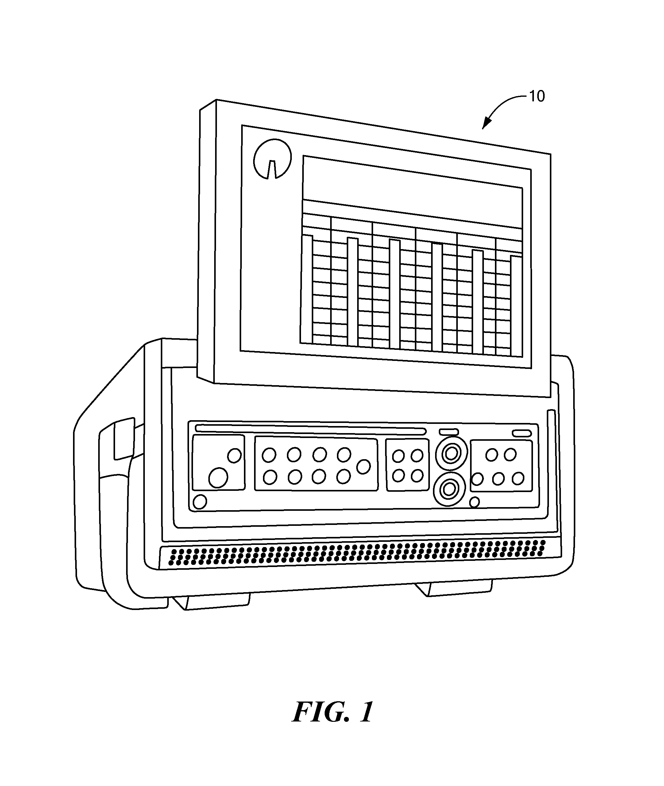
[0023]Referring now to the drawings in which like reference designators refer to like elements, there is shown in FIG. 1 an exemplary embodiment of a control unit such as for example an RF generator constructed in accordance with the principles of the present invention, designated generally as 10. Of note, the device components have been represented where appropriate by conventional symbols in the drawings, showing only those specific details that are pertinent to understanding the embodiments of the present invention so as not to obscure the disclosure with details that will be readily apparent to those of ordinary skill in the art having the benefit of the description herein. Moreover, while certain embodiments or figures described herein may illustrate features not expressly indicated on other figures or embodiments, it is understood that the features and components of the system and devices disclosed herein may be included in a variety of different combinations or configurations...


PUM


Abstract

A method and system for detecting microbubble formation during a radiofrequency ablation procedure. The method includes measuring an impedance of a pair of electrodes, at least one electrode in the pair of electrodes being coupled to a treatment assembly of a medical device. Radiofrequency ablation energy is transmitted between the pair of electrodes. The transmission of radiofrequency ablation energy between the pair of electrodes is terminated when after a predetermined period of time the measured impedance in either of the electrodes in the pair of electrodes is a predetermined percentage above a measured minimum impedance and a measured power is above a predetermined power threshold. An alert is generated indicating at least one of the formation and release of microbubbles proximate the pair of electrodes.

Description

CROSS-REFERENCE TO RELATED APPLICATION[0001]n / aSTATEMENT REGARDING FEDERALLY SPONSORED RESEARCH OR DEVELOPMENT[0002]n / aFIELD OF THE INVENTION[0003]The present invention relates to a method and system for detecting microbubbles during an ablation procedure.BACKGROUND OF THE INVENTION[0004]Current radiofrequency ablation (“RF”) devices are constructed in a variety of configurations to target specific maladies and to provide for specific treatment protocols. In particular, many RF ablation devices have one or more treatment regions in which multiple treatment electrodes are disposed and are torqueable, or otherwise manipulatable, into a variety of different geometric configurations to treat particular cardiovascular tissues. For example, treatment electrodes may be coupled to an array or a carrier assembly manipulatable to define substantially linear, helical, and circular configurations depending on the desired treatment to be performed. In such multi-electrode configurations, each ad...

Claims


Application Information

Patent Timeline
22 Dec 2015
Publication
US9216050B2
IPC
A61B18/12; A61B18/00; A61B18/14
CPC
A61B18/1206; A61B18/1492; A61B2018/00267; A61B2018/00577; A61B2018/00642; A61B2018/00898; A61B2018/00678; A61B2018/00702
Inventors
CONDIE, CATHERINE R.; SHERMAN, MARSHALL L.