Buck converter with reverse current protection, and a photovoltaic system

a reverse current protection and converter technology, applied in the direction of pulse technique, process and machine control, instruments, etc., can solve the problems of power being dissipated in the diode, series diodes have a significant voltage drop in normal operation, damage to the converter, etc., and achieve the effect of ensuring the proper operation of the protection switch

Active Publication Date: 2015-12-22
NXP BV
View PDF12 Cites 3 Cited by
  • Summary
  • Abstract
  • Description
  • Claims
  • Application Information

AI Technical Summary

Benefits of technology

[0010]The anti-series configuration of the high-side switch and the protection switch operates to prevent reverse currents through the high-side switch and low-side switch. The use of a shutter switch to control the protection switch is particularly convenient and inexpensive. Further, and in contrast to use of a control block to control both the protection switch in and the high-side and low-side switches, according to embodiments, even if the converter is not operational and any battery that is connected to the output is discharged, there may be control of the output voltage and it may be that proper operation of the protection switch can be guaranteed. The shutter switch according to embodiments may be capable of controlling the protection switch to prevent reverse currents from both ground and the output, even when the buck converter is inactive, because it makes the protection switch work for Vout>=Vin. Yet further, it may be possible to use a low-voltage transistor for the protection switch, without the requirement for any level shifters.

Problems solved by technology

If switches 1 and 2 are low-ohmic, which is typically the case for high efficiency converters, the resulting current may be high and lead to damage to the converter.
The series diode however has a significant voltage drop in normal operation, when it is forward biased.
This results in power being dissipated in the diode which can have a significant impact on the efficiency of the buck converter, especially when low-ohmic power switches are used.

Method used


Image

  • Buck converter with reverse current protection, and a photovoltaic system
  • Buck converter with reverse current protection, and a photovoltaic system
  • Buck converter with reverse current protection, and a photovoltaic system

Examples


Embodiment Construction

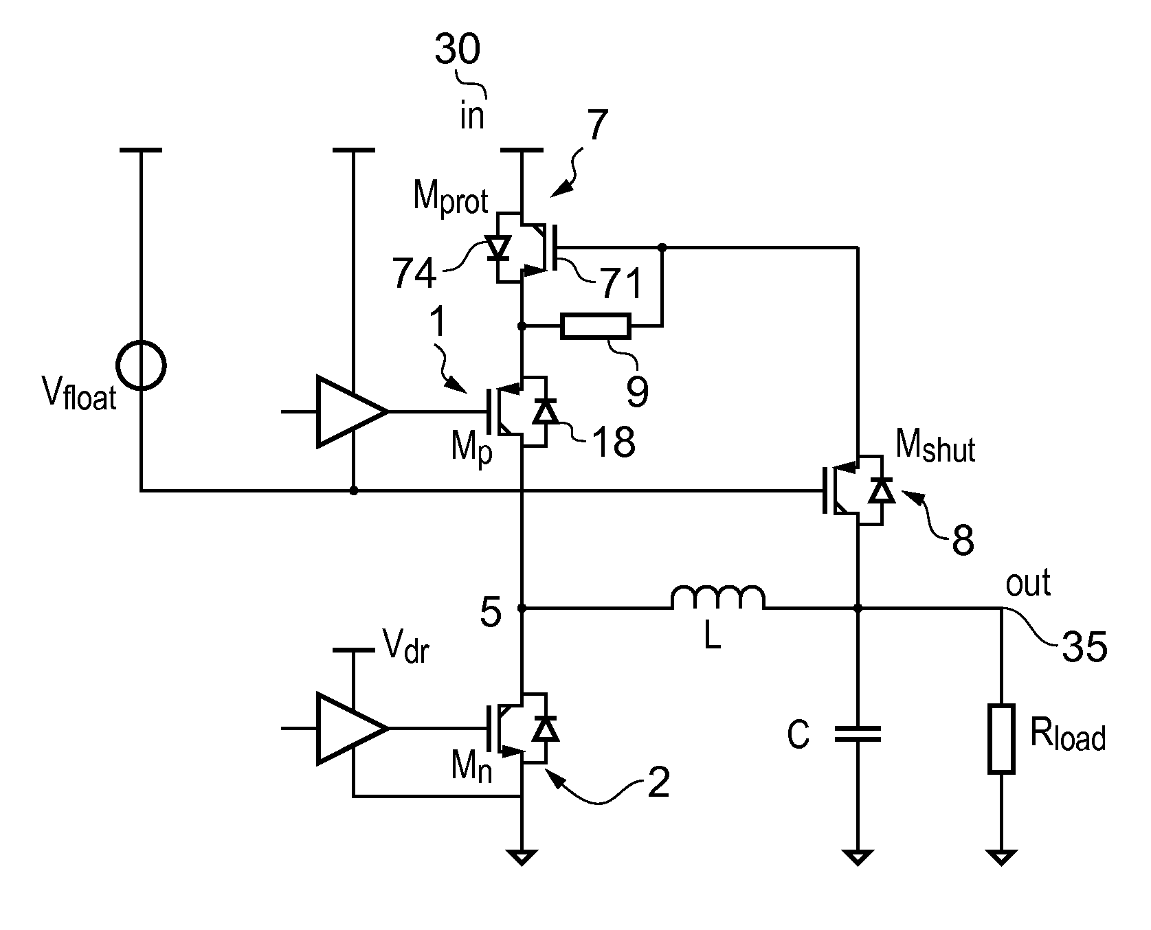
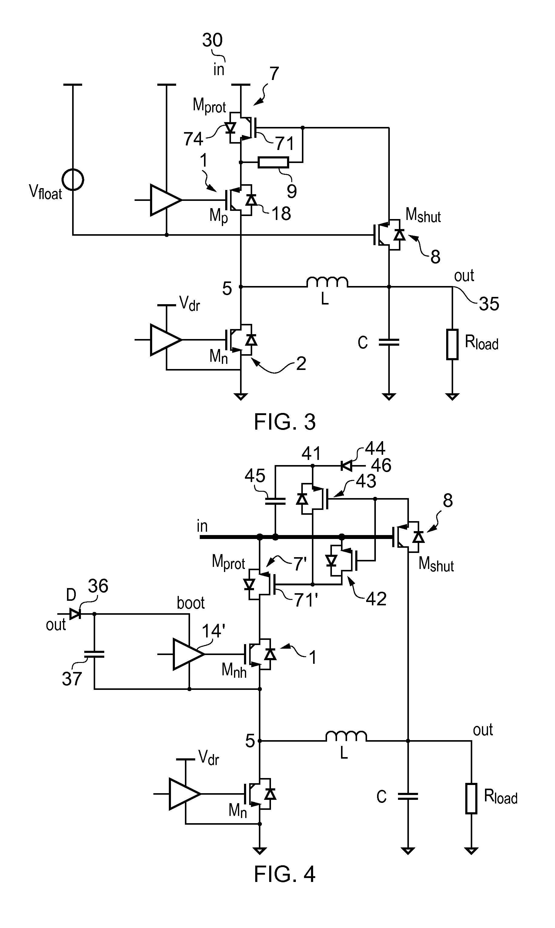
[0026]An example of a buck converter, for converting an input voltage Vin to an output voltage Vout, according to embodiments, is shown in FIG. 3. The buck converter shown in FIG. 3 includes a protection switch 7, which is connected in anti-series with the high-side switch 1 and between the high-side switch and the supply 30. By ‘anti-series’ is meant that the body diode 74 of the protection switch 7 is arranged with the opposite polarity to the polarity of the body diode 18 of the high-side switch 1. The protection switch may be dimensioned so as to have a low on-resistance in order to reduce its conduction losses. Further, the dimensions of the protection switch may be relatively small, since a low-voltage switch can be used and as the skilled person will appreciate, in general, the size of switch scales approximately quadratically with its voltage rating. (As shown in FIG. 3, the protection switch need not be a high voltage switch, whereas the high-side and low-side switches of t...


PUM


Abstract

A buck converter is disclosed comprising a series combination of high-side and low-side switches, and including a protection switch in anti-series with the high-side switch. The protection switch is controlled by means of a shutter switch, which is powered from the output of the converter and gated from the half bridge node of the converter. Also disclosed is a photovoltaic system comprising such a buck converter and a solar panel.

Description

CROSS-REFERENCE TO RELATED APPLICATIONS[0001]This application claims the priority under 35 U.S.C. §119 of European patent application no. 12171141.0, filed on Jun. 7, 2012, the contents of which are incorporated by reference herein.FIELD OF THE INVENTION[0002]This invention relates to buck converters.BACKGROUND OF THE INVENTION[0003]Buck converters are generally used to transform a relatively higher DC voltage into a relatively lower DC voltage. An example of a buck converter is shown in FIG. 1. The converter comprises a high-side switch Mp 1 and a low-side switch Mn 2 connected in series between a supply 30 and a ground 4. The control terminal 11 of the high-side switch 1 is controlled by means of a switch controller 14, and the control terminal 21 of the low side switch to is controlled by switch controller 24. The switches are closed in alternation such that the half-bridge node 5 therebetween is alternately connected to supply 30 and to ground 4. An output filter consisting of a...

Claims


Application Information

Patent Timeline
Patent Type & Authority Patents(United States)
IPC IPC(8): G05F1/56H02M3/156H02M1/32H02M3/158H03K17/0814G05F1/565
CPCH02M3/156H02M1/32H02M3/1588H03K17/08142Y02E10/56G05F1/565Y02B70/1466Y02B70/10
Inventor DOORN, TOBIAS SEBASTIAAN
Owner NXP BV
Why Eureka
Try Eureka