Deflector for marine data acquisition system

a data acquisition system and deflector technology, applied in seismology, geological measurements, seismology for water-covered areas, etc., can solve problems such as low stability, and achieve the effect of improving angular stability

Active Publication Date: 2015-12-29
CGGVERITAS SERVICES
View PDF16 Cites 8 Cited by
  • Summary
  • Abstract
  • Description
  • Claims
  • Application Information

AI Technical Summary

Benefits of technology

[0009]One objective achieved in some of the embodiments described in this application is to provide a deflector with improved angular stability for marine survey (i.e., data acquisition) systems. That is, deflectors are configured to develop a restoring torque opposing deviations (pitch, roll and yaw) of the deflector from an intended position.

Problems solved by technology

While this profile does not provide an accurate location of oil and gas reservoirs, it suggests, to those trained in the field, the presence or absence of these reservoirs.
A problem with the conventional deflector is that its angular stability is low, that is, if it rotates (e.g., due to currents) around the towing position, the deflector does not return to the intended position, and, therefore, instead of providing a lift force, drags down the towing cable. FIGS. 2A and 2B illustrate this problem.

Method used


Image

  • Deflector for marine data acquisition system
  • Deflector for marine data acquisition system
  • Deflector for marine data acquisition system

Examples


Embodiment Construction

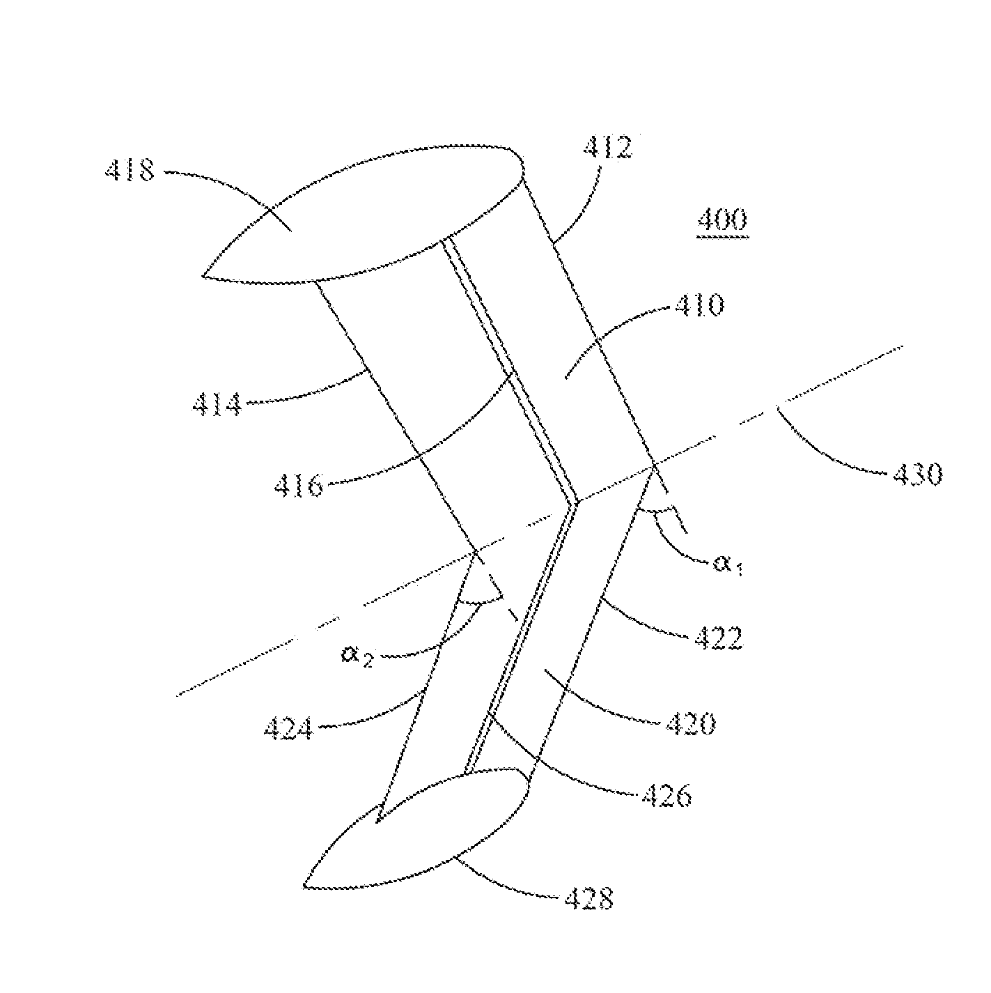
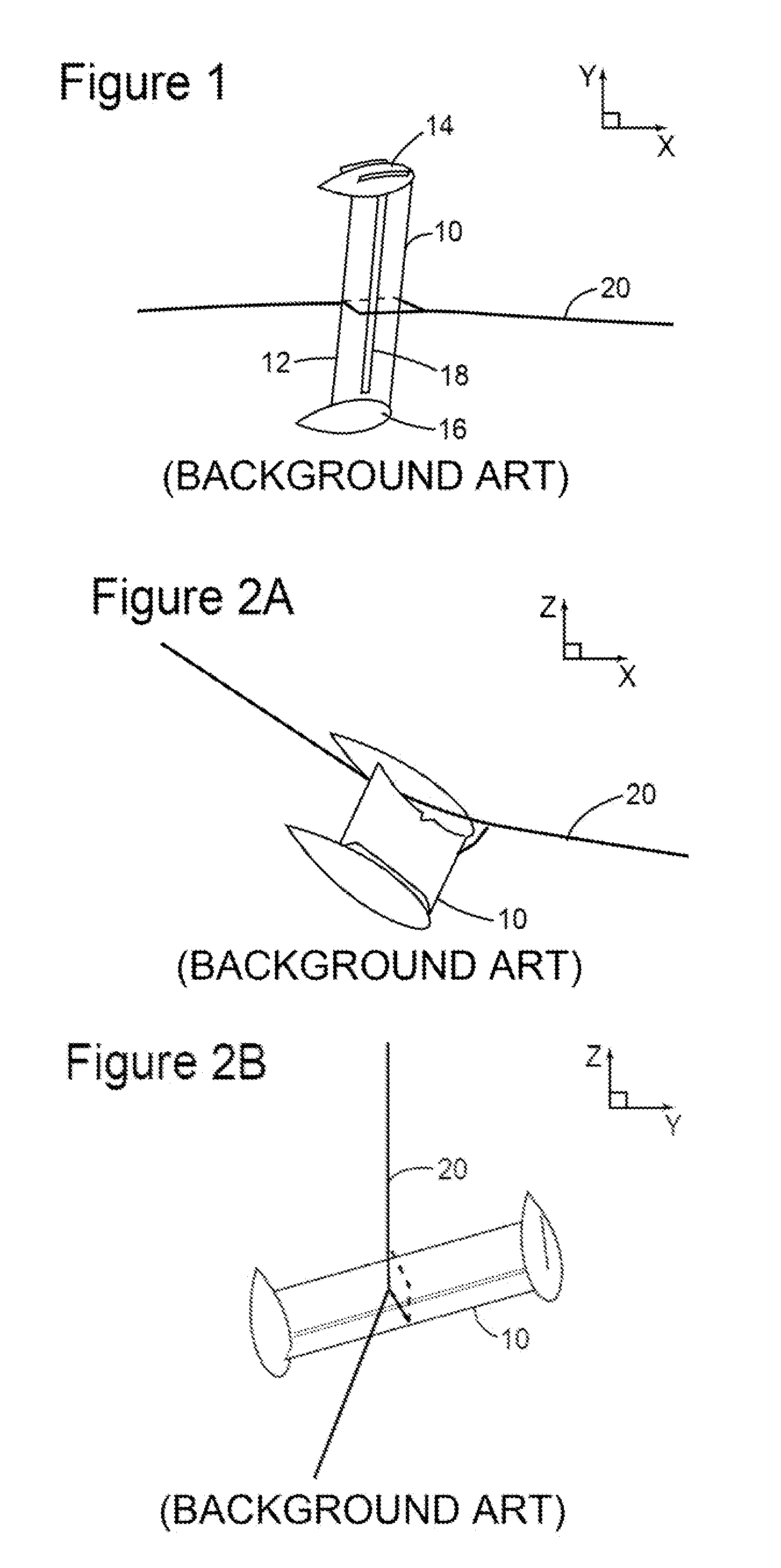
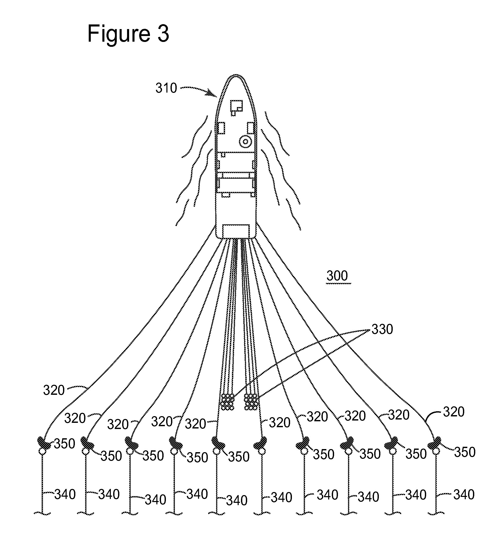
[0022]The following description of the exemplary embodiments refers to the accompanying drawings. The same reference numbers in different drawings identify the same or similar elements. The following detailed description does not limit the invention. Instead, the scope of the invention is defined by the appended claims. The following embodiments are discussed, for simplicity, with regard to the terminology and structure of a marine survey data acquisition system having one or more cables towed by a vessel. However, the embodiments to be discussed next are not limited to this structure, but they may be applied to other situations in which cables are towed in water at a predetermined depth.

[0023]Reference throughout the specification to “one embodiment” or “an embodiment” means that a particular feature, structure or characteristic described in connection with an embodiment is included in at least one embodiment of the subject matter disclosed. Thus, the appearance of the phrases “in ...


PUM


Abstract

Deflectors configured to be attached to cables towed behind a vessel for performing a marine survey are provided. A deflector has a wing body including a first part joined to a second part to form a swept-back-wing shape, the first part and the second part being substantially coplanar. A first straight line stretching along at least a portion of a front edge of the first part makes a first angle with a second straight line stretching along at least a portion of a front edge of the second part. A third straight line stretching along at least a portion of a trailing edge of the first part makes a second angle with a fourth straight line stretching along at least a portion of a trailing edge of the second part, the first angle and the second angle being non-zero angles.

Description

BACKGROUND[0001]1. Technical Field[0002]Embodiments of the subject matter disclosed herein generally relate to devices and systems used for marine exploration and, more particularly, to deflectors attached to cables that carry seismic instrumentation.[0003]2. Discussion of the Background[0004]Marine data acquisition and processing generate a profile (image) of a geophysical structure under the seafloor. While this profile does not provide an accurate location of oil and gas reservoirs, it suggests, to those trained in the field, the presence or absence of these reservoirs. In order to obtain a high-resolution image of the structure under the seafloor, plural techniques and devices are employed to maintain the data acquisition geometry while scanning the targeted area.[0005]In marine exploration, waves (such as, but not limited to, seismic waves) are directed toward the seabed, and waves reflected back to receivers close to the water surface are used to extract information about the ...

Claims


Application Information

Patent Timeline
Patent Type & Authority Patents(United States)
IPC IPC(8): B63B21/66G01V1/38
CPCB63B21/663B63B21/66G01V1/3826G01V1/3817G01V1/38
Inventor RICHER DE FORGES, HERVE
Owner CGGVERITAS SERVICES
Why Eureka
Try Eureka