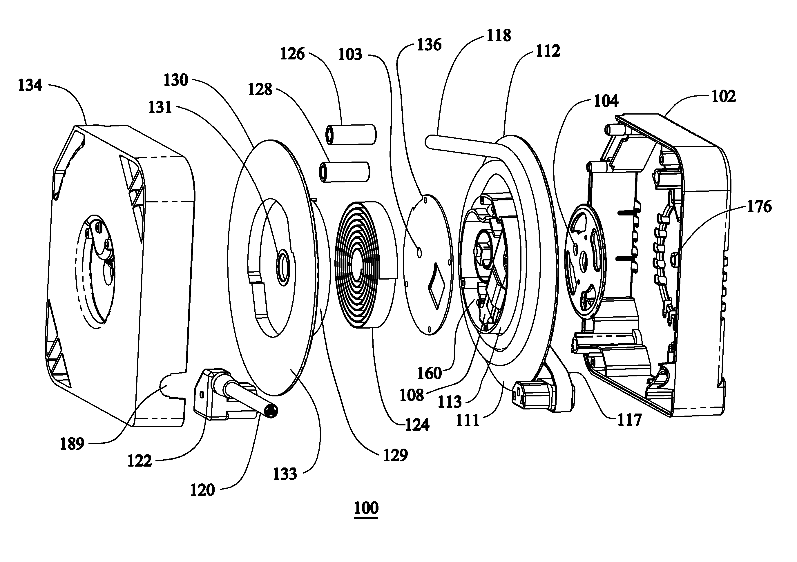
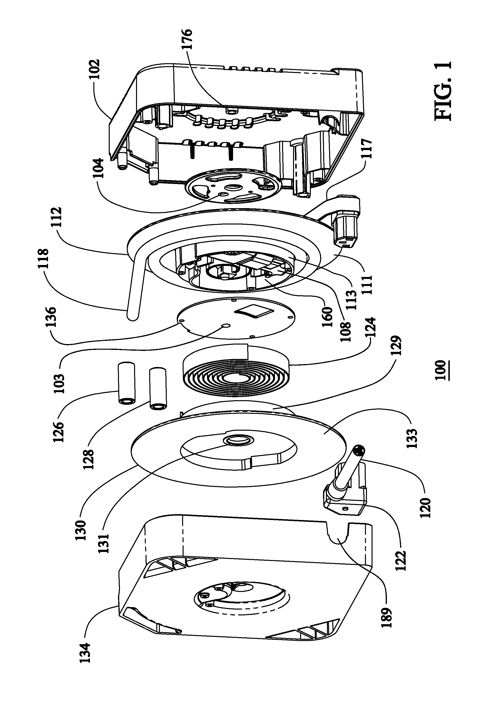
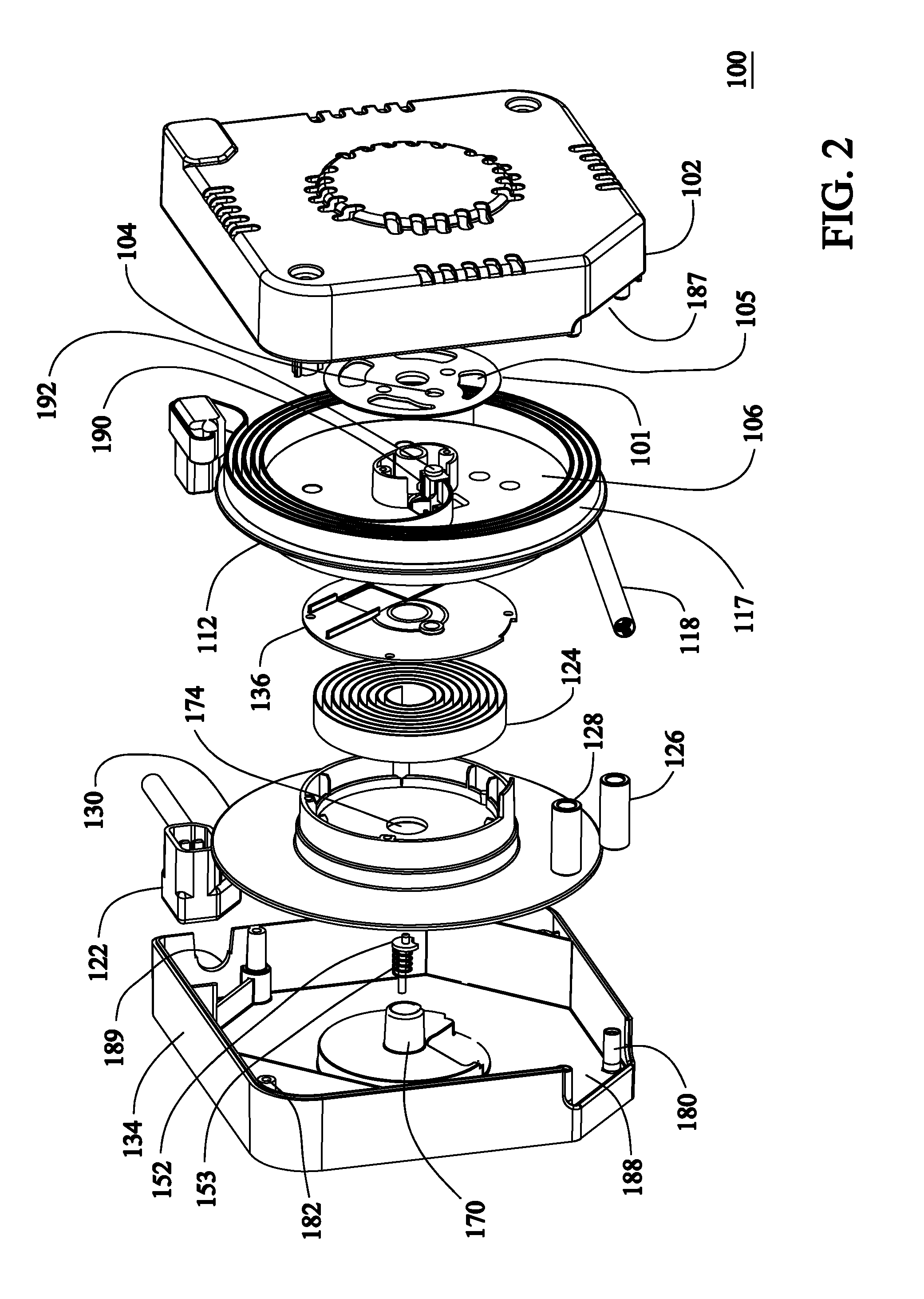
Rotatable cable guide for retractable cord reel

a retractable, cable guide technology, applied in the direction of etc., can solve the problems of corroding contacts in brush and slip ring cord reels, accumulating dirt, open circuit, etc., to remove excessive axial clearance and enhance biasing

Inactive Publication Date: 2015-12-29
RESPONSE ENG
View PDF25 Cites 5 Cited by
  • Summary
  • Abstract
  • Description
  • Claims
  • Application Information

AI Technical Summary

Benefits of technology

[0015]The expansion of the flat cable within the expansion chamber may be configured to allow the flat cable to wind back around the spool in a reverse direction after expansion. This unwinding and winding reduces the length of cable needed in the expansion chamber by approximately half, thereby providing a superior product that weighs less, costs less, has less conductive resistance and dissipates less heat.
[0028]Still another variation would be a cord reel that uses the natural tendency of a power spring to expand axially as it is wound from rotation. Placing the power spring such that one side is in contact with the spool and the side located axially opposite bears directly or indirectly against the housing causes the power spring to push the two apart resulting in the desired axially biasing of the spool. This biasing can be enhanced by manufacturing the spring such that in its natural state the center of the spring is axially displaced from the outer diameter of the spring causing the spring to be somewhat conical. This spring can perform both the axial biasing of the spool to remove clearances without the need for a plunger, and at the same time, the rotational biasing of the spool to retract the cords.

Problems solved by technology

Such a configuration reduces the mess typically associated with loose wires, as well as dangers related to loose cords which can, for example, become damaged creating electrical hazards or get in the way such as becoming a tripping hazard.
The sliding contacts in a brush and slip ring cord reel can corrode, wear out, accumulate dirt or encounter other problems that may interfere with proper conduction of electricity or electrical signals.
This is particularly a problem at low voltages where electricity is unable to arc through a small gap or dirt and result in an open circuit.
Cord reels such as shown in U.S. Pat. No. 8,123,010 with inventors Richard Skowronski et al, which have contacts on a ratchet that engage only when the spool is locked from rotation, avoid some of the wear and dirt accumulation issues but they do not provide continuous continuity during extension and retraction of the retractable cable.
Additionally, both the brush / slip ring cord reels and the contacts-on-ratchet cord reels can potentially cause sparks as the contacts rub which can be a problem in wet or potentially explosive environments.
Unfortunately these cord reels have a very short service life because the internal cable is forced to bend sharply back and forth as the retractable cord is extended and retracted, resulting in early failure of the internal cable.

Method used


Image

  • Rotatable cable guide for retractable cord reel
  • Rotatable cable guide for retractable cord reel
  • Rotatable cable guide for retractable cord reel

Examples


Embodiment Construction

Non-Limiting Examples and Terminology

[0046]As required, detailed embodiments of the present invention are disclosed herein; however, it is to be understood that the disclosed embodiments are merely examples of the invention, which can be embodied in various forms. Therefore, specific structural and functional details disclosed herein are not to be interpreted as limiting, but merely as a basis for the claims and as a representative basis for teaching one skilled in the art to variously employ the present invention in virtually any appropriately detailed structure and function. Further, the terms and phrases used herein are not intended to be limiting; but rather, to provide an understandable description of the invention.

[0047]The terms “a” or “an”, as used herein, are defined as one or more than one. The term plurality, as used herein, is defined as two or more than two. The term another, as used herein, is defined as at least a second or more. The terms including and / or having, as ...


PUM


Abstract

A novel retractable cord reel is disclosed. The retractable cord reel may have a rotating rotatable guide configured to adapt to an expandable wire coil that changes direction within the cord reel. The retractable cord reel may have splices between wire segments that are formed by electrical connectors that are sealed from the environment with an adhesive.

Description

CROSS-REFERENCE TO RELATED APPLICATIONS[0001]This application is a continuation-in-part of and claims priority from prior U.S. Provisional Patent Application No. U.S. 61 / 852,580, filed on Mar. 18, 2013, the entire disclosure of which application is incorporated by reference in its entirety.FIELD OF THE INVENTION[0002]The present invention relates generally to a retractable cord reel apparatus, and more specifically relates to a retractable cord reel with wire or cable management.BACKGROUND OF THE INVENTION[0003]Retractable cord reels have been used in various applications to retractably store various types of wires, cords and cables. Typically, a reel might have a stationary end and a retractable end. The retractable end is typically wound on a rotating spool within the cord reel which carries a wire or cable capable of extension from and retraction back into the reel as the cord is unwound from then rewound back onto the rotating spool. The stationary end does not move during exten...

Claims


Application Information

Patent Timeline
Patent Type & Authority Patents(United States)
IPC IPC(8): B65H75/00B65H75/44
CPCB65H75/4449B65H2701/34
Inventor SKOWRONSKI, RICHARD
Owner RESPONSE ENG
Why Eureka
Try Eureka