Monitoring an optical element of a processing head of a machine for thermal processing of a workpiece

a technology of thermal processing and monitoring elements, which is applied in the direction of optical elements, instruments, optics, etc., can solve the problems of increasing the number of optical elements, increasing the susceptibility of the apparatus, and soiling the surface of the optical element, so as to facilitate the exchange of optical elements and/or associated monitoring elements, reduce the susceptibility of the apparatus, and reduce the length of the cable in the apparatus

Active Publication Date: 2006-01-19
TRUMPF LASER GMBH CO KG
View PDF5 Cites 4 Cited by
  • Summary
  • Abstract
  • Description
  • Claims
  • Application Information

AI Technical Summary

Benefits of technology

[0010] A cartridge can be provided for holding the optical elements, and the cartridge can be plugged into and unplugged from a processing head of the machine. The detector can also be mounted to the cartridge. Such an arrangement facilitates exchange of the optical element and / or associated monitoring elements. Connecting bores in the cartridge between the optical elements and the detectors are closed by glass plugs to prevent dirt or dust particles from entering the cartridge.
[0011] Electronics for evaluation of the intensity of the scattered light beam can also be disposed on the cartridge, which reduces the susceptibility of the apparatus to mechanical and electrical disturbances and reduces cable lengths in the apparatus. The electronics can also include a storage medium for storing correction and calibration data.

Problems solved by technology

The splashes and smoke may be deposited on a surface of an optical element that faces the workpiece of the processing head of the machine and may soil the surface of the optical element.
Deposits on or damage to the optical surface can result in an increased absorption of the laser radiation by the optical element.
Accordingly, the thermal load of the optical element increases, which results in a noticeable decrease of the laser power available in the processing region.
In case of heavy soiling, in particular, through splashes, increased absorption of the laser radiation can result in the destruction of the optical element.
Disturbances through reverse reflection from the workpiece, welding flares, external light etc., however, disturb the evaluation signal, because these disturbances affect only the protective glass and not the element providing the reference.
The linear evaluation may cause problems with regard to overloading or underloading during evaluation.
Detection of soiling through smoke in this way may be inaccurate because smoke produces only very little stray light on the protective glass edge.

Method used


Image

  • Monitoring an optical element of a processing head of a machine for thermal processing of a workpiece
  • Monitoring an optical element of a processing head of a machine for thermal processing of a workpiece
  • Monitoring an optical element of a processing head of a machine for thermal processing of a workpiece

Examples


Embodiment Construction

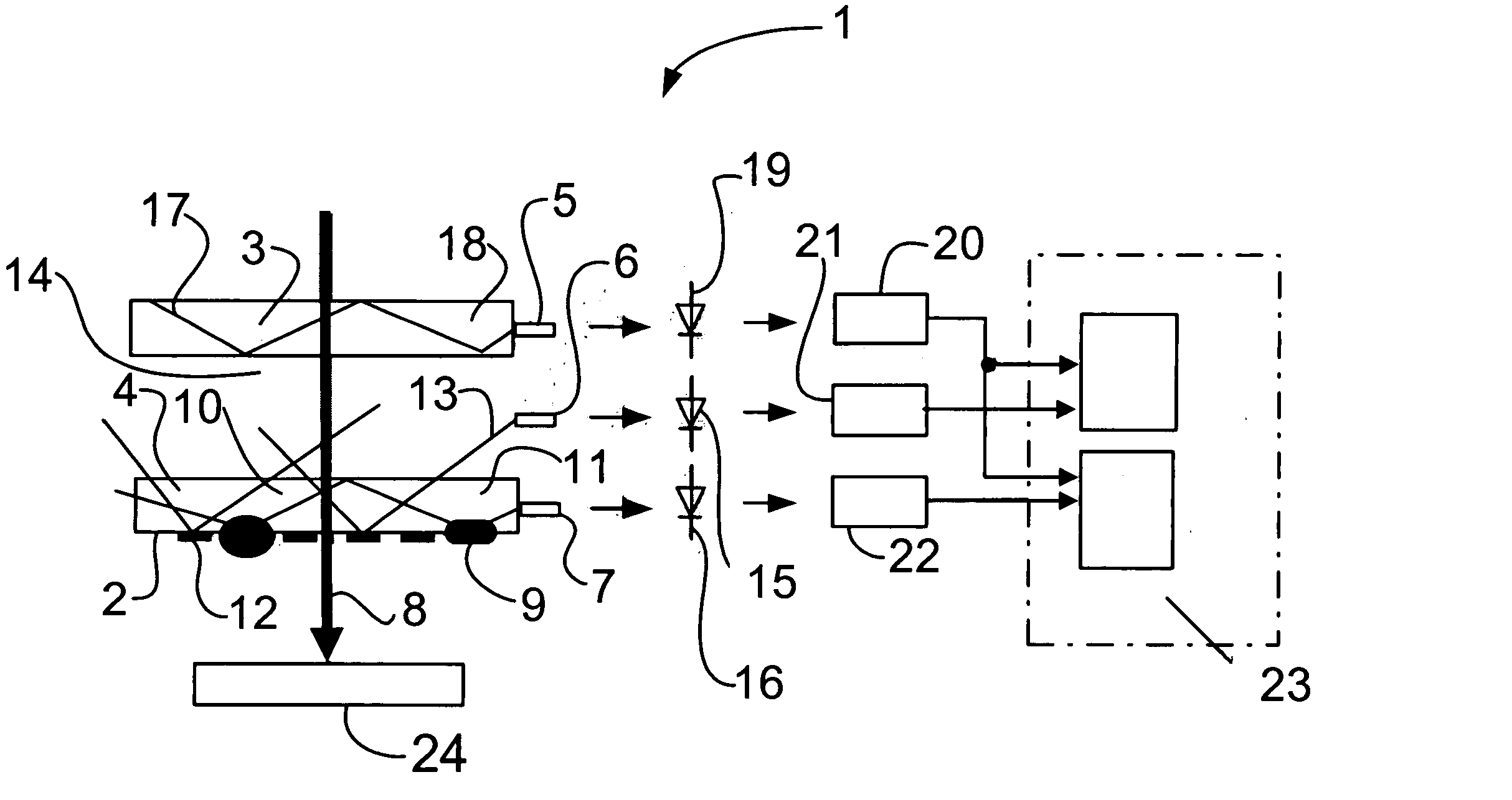
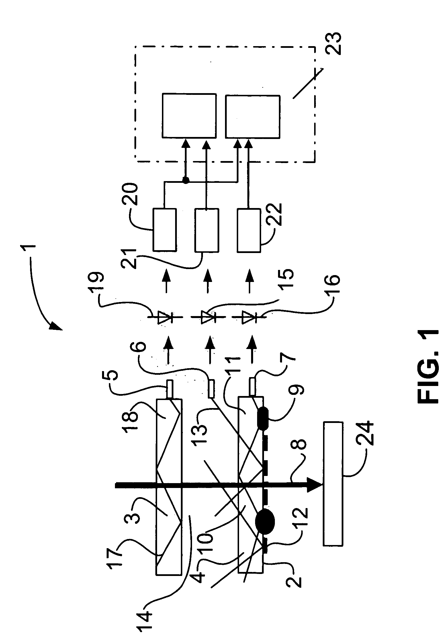
[0026] As is shown in FIG. 1, an apparatus 1 for monitoring the soiling of an optical surface 2 includes a first protective glass 3, a second protective glass 4, three glass plugs 5, 6, and 7, and three sensors 15, 16, and 19 for detecting stray light. The optical elements of the apparatus 1 (i.e., the first protective glass 3 and the second protective glass 4) can be flat slides but can also be lenses, partially-reflecting mirrors or other optical elements. The protective glasses 3 and 4 can be held in a cartridge such that they can be easily exchanged by the operator (as explained in more detail below).

[0027] A focused laser beam 8 emitted by a processing head (not shown) of a laser processing machine impinges on a workpiece 24 for processing the workpiece. During processing of the workpiece 24, the second protective glass 4 can be soiled, which results in reduced laser beam power reaching the workpiece 24 and decreased processing of the workpiece 24. If processing of the workpie...


PUM

PropertyMeasurementUnit
transparentaaaaaaaaaa
thermal poweraaaaaaaaaa
opticalaaaaaaaaaa

Abstract

An apparatus for monitoring soiling of an optical element of a processing head of a machine for laser processing of a workpiece includes a first transparent optical element, positioned in a path of a laser beam, a second transparent optical element, positioned in the path of a laser beam and separated from the first transparent optical element by a gap, a first detector for detecting laser light scattered from the first transparent optical element, and a second detector for detecting laser light scattered within the gap between the first transparent optical element and the second transparent optical element.

Description

TECHNICAL FIELD [0001] This invention relates to thermal processing machines and, in particular, to monitoring an optical element of a processing head of a machine for thermal processing of a workpiece. BACKGROUND OF THE INVENTION [0002] German patent number DE 195 07 401 A1 discloses monitoring soiling of a protective glass through reference measurement on a first optical element and measurement of a soiled second optical element. [0003] During the processing of workpieces with a machine for thermal welding or cutting, (e.g., a laser processing machine) splashes and smoke are produced in the processing region of the workpiece. The splashes and smoke may be deposited on a surface of an optical element that faces the workpiece of the processing head of the machine and may soil the surface of the optical element. The splashes may be burnt into the optical surface. Smoke can be deposited on the optical surface but can be removed from the optical surface to a certain extent. Deposits on...

Claims


Application Information

Patent Timeline
Patent Type & Authority Applications(United States)
IPC IPC(8): G01N21/88
CPCG01N21/15G01N2021/157G01N21/94G01N21/47
Inventor FLAIG, RAINER
Owner TRUMPF LASER GMBH CO KG
Why Eureka
Try Eureka