Engine augmentation of hydraulic control system

a hydraulic control system and engine technology, applied in the direction of fluid couplings, couplings, rotary clutches, etc., can solve the problems of inflexibility in implementing different control strategies, inefficient valve systems in terms of energy dissipation across valves, loss of energy, etc., and achieve the effect of reducing demand and saving energy consumption

Inactive Publication Date: 2015-12-29
CONCENTRIC ROCKFORD
View PDF3 Cites 1 Cited by
  • Summary
  • Abstract
  • Description
  • Claims
  • Application Information

AI Technical Summary

Benefits of technology

[0006]In order to reduce the operating forces required by a valve, it is known to utilize a servo valve in which a pilot operation is used to control the fluid flow. In such an arrangement, a pilot valve balances a pair of pilot flows and can be moved to increase one flow and decrease the other. The change in flows is used to move a control valve and operate the hydraulic device. The force required to move the pilot valve is less than that required for the control valve and therefore enhanced control is obtained. However, there is a continuous flow at high pressure through the pilot valve resulting in significant losses. The control valve itself also suffers deficiencies of energy loss due to metering flow across restrictive ports and therefore, although it offers enhanced control, the energy losses are significant.
[0007]In U.S. Pat. No. 7,516,613 there is disclosed a hydraulic transmission system in which variable capacity hydraulic machines are used to control movement of actuators along or about defined axes. The machines are driven from a prime mover through a mechanical transmission that allows power to be transferred from one machine to another. This permits energy recovered from the operations of one of the hydraulic machines to be redirected to a machine that is consuming energy, offering a saving in the energy consumption from the prime mover. In one of the embodiments described, a hydraulic accumulator is provided to store energy and subsequently supply energy to the transmission. The accumulator is connected to the transmission through a reversible, variable capacity hydraulic machine that is controlled to allow energy to flow to and from the accumulator. Control of the variable capacity hydraulic machine reduces the demand on the prime mover, allowing it to operate under steady state conditions for periods of time.

Problems solved by technology

Such valve systems are relatively inefficient in terms of the energy dissipated across the valve.
In an open centre arrangement, careful manufacture of the valve is required in order to obtain the transition between the zero flow and full flow whilst retaining control of the load and metering of the flow across the valve causes loss of energy.
As such, the valves tend to be specialized and do not offer flexibility in implementing different control strategies.
Most significantly, since the control is achieved by metering flow across an orifice there is inherently significant energy loss when controlling fluid flow.
Because the control valve is typically a one piece spool, a similar restricted port is presented to the exhaust flow and results in a significant energy loss.
However, there is a continuous flow at high pressure through the pilot valve resulting in significant losses.
The control valve itself also suffers deficiencies of energy loss due to metering flow across restrictive ports and therefore, although it offers enhanced control, the energy losses are significant.

Method used


Image

  • Engine augmentation of hydraulic control system
  • Engine augmentation of hydraulic control system
  • Engine augmentation of hydraulic control system

Examples


Embodiment Construction

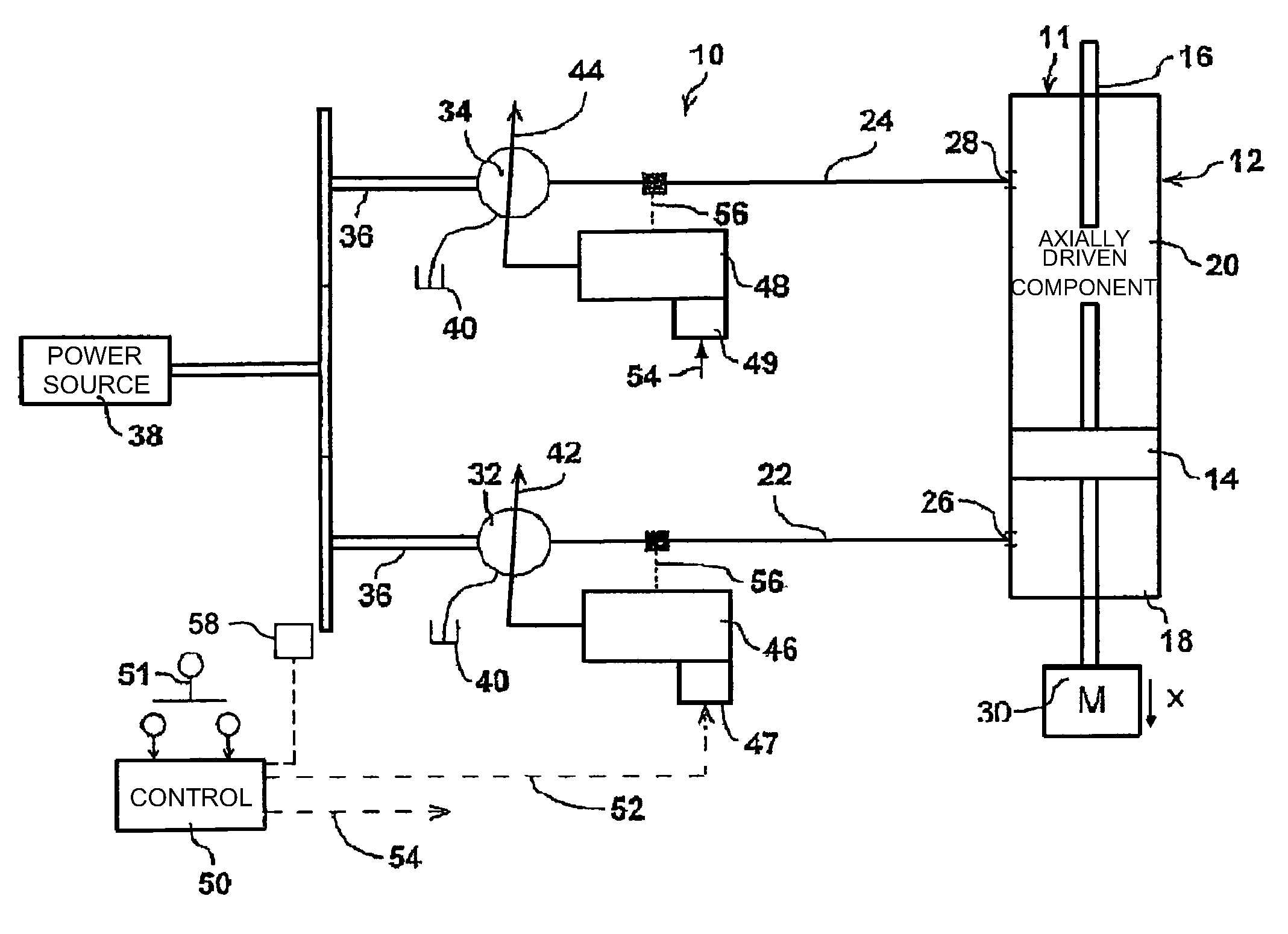
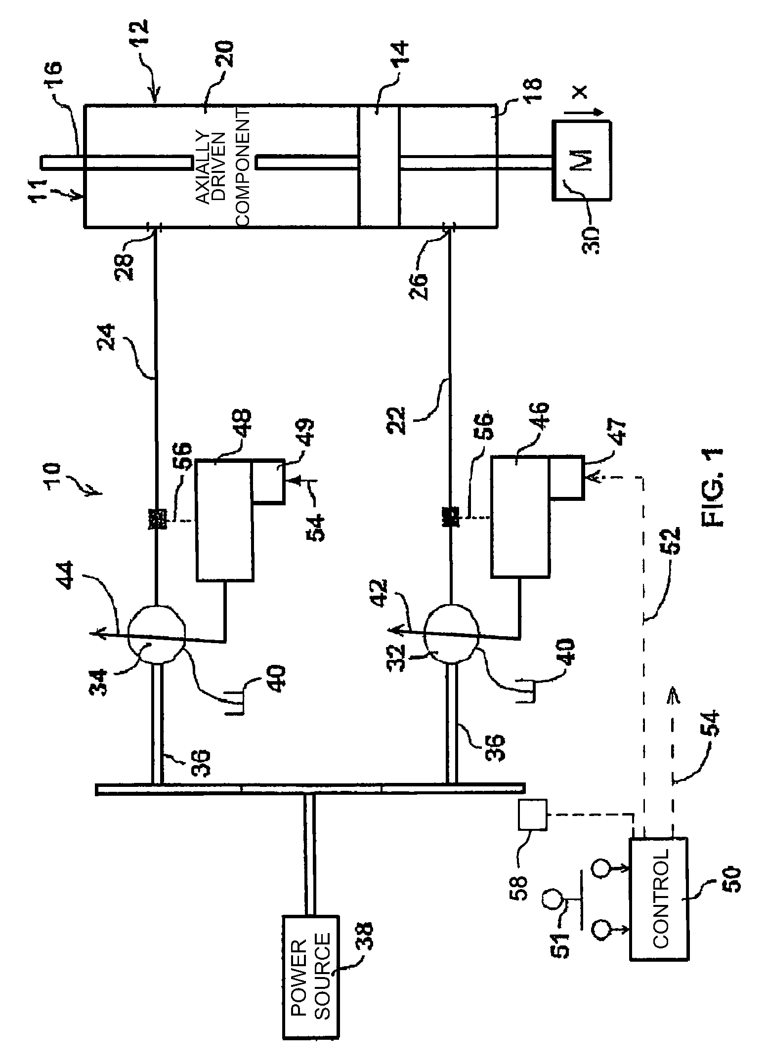
[0025]To facilitate a full understanding of the operation of the energy transmission system, different configurations of hydraulic transmission will first be explained in the manner set out in U.S. Pat. No. 7,516,613. Thereafter, the integration of the control of the hydraulic transmission with that of the prime mover will be described. Referring therefore to FIG. 1, a hydraulic drive system 10 includes an actuator 11 having a cylinder 12 with a piston 14 supported within the cylinder 12. The piston 14 is connected to a piston rod 16 that extends from opposite ends of the cylinder 12. The piston 14 subdivides the cylinder 12 into chambers 18 and 20 which are connected to supply lines 22, 24 by ports 26, 28 respectively. The rod 16 is connected to a load 30 shown schematically as a horizontal sliding mass.

[0026]The supply lines 22, 24 are connected to the outlets of a pair of variable capacity hydraulic machines 32, 34. The machines 32, 34 are typically a swashplate device in which t...


PUM


Abstract

A power distribution system includes a prime mover and a hydraulic drive system. The hydraulic drive system includes an accumulator to store energy and supplement that available from the prime mover. A control monitors torque imposed on the prime mover and utilizes energy stored in the accumulator to offload the prime mover when its operating conditions are to be changed. Effecting a change under reduced load conditions mitigates inefficient operation of the prime mover.

Description

CROSS REFERENCE[0001]The present application claims the benefit under 35 U.S.C. §119(e) of the U.S. Provisional Patent Application Ser. No. 61 / 476,675, filed on Apr. 18, 2011, the content of which is incorporated herein by reference.FIELD OF THE INVENTION[0002]The present invention relates to energy transmission systems and more particularly to such systems utilizing hydraulic fluid as an energy transfer medium.SUMMARY OF THE INVENTION[0003]It is well-known to transfer energy from a source such as a motor or internal combustion engine to a load through the intermediary of hydraulic drive system. Such systems will typically have a pump driven by the source and a motor connected to the load. By adjusting the hydraulic flow between the pump and the motor it is possible to impart movement to the load, maintain it in a fixed position and otherwise influence its disposition.[0004]The control of fluid flow is typically accomplished by a valve mechanism, which in its simplest form simply op...

Claims


Application Information

Patent Timeline
Patent Type & Authority Patents(United States)
IPC IPC(8): F16D31/02F15B1/02F15B21/14
CPCF15B1/02F15B21/14F15B2211/20523F15B2211/20546F15B2211/88F15B2211/20576F15B2211/27F15B2211/625F15B2211/633F15B2211/20569F15B1/024F15B2211/20507F15B2211/6651
Inventor KADLICKO, GEORGEGREGORIO, JOHNGIMBER, TOBINMANEY, JEFFREY
Owner CONCENTRIC ROCKFORD
Why Eureka
Try Eureka