Connector and switch

a technology of connecting wires and switches, applied in the direction of coupling devices, two-part coupling devices, electrical equipment, etc., can solve the problem that the connection in which a currently used switch is assembled cannot be used without modification, and achieve the effect of safe supply, better safety and better reliability

Active Publication Date: 2015-12-29
NTT FACILITIES INC +1
View PDF14 Cites 7 Cited by
  • Summary
  • Abstract
  • Description
  • Claims
  • Application Information

AI Technical Summary

Benefits of technology

[0033]According to the aspects of conducting the present invention, it is possible to provide a connector for high voltage electric power higher than the voltage of a currently used commercial power source or for a direct current power source so that electric power is safely supplied from these power sources. Further, it is possible to provide a switch having better safety and better reliability for a high voltage power source having a voltage higher than the voltage of a currently used commercial power source or for a direct current power source.

Problems solved by technology

Especially, such direct current power supply may be desirable in an information apparatus such as a server since the information apparatus may consume great electric power.
For example, a connector in which a currently used switch is assembled cannot be used without modification in a case where a voltage becomes 100 V or greater or a high voltage direct current is used.
In a case where electric power supplied from the power source is a direct current of 400 V, because sufficient safety or reliability is not assured in a switch used for a currently used alternate current (AC) 100 V, the use of the currently used switch may cause danger.

Method used


Image

  • Connector and switch
  • Connector and switch
  • Connector and switch

Examples


first embodiment

(Structure of Connectors)

[0079]The structure of the connector of a first embodiment is described.

[0080]The connector of the first embodiment is connected to another connector being a plug connector illustrated in FIGS. 1 to 5. The connector of the first embodiment corresponds to a jack connector having a structure illustrated in FIGS. 6 to 8. Hereinafter, the plug connector illustrated in FIGS. 1 to 5 and the jack connector illustrated in FIGS. 6 to 8 may be collectively referred to as a connector.

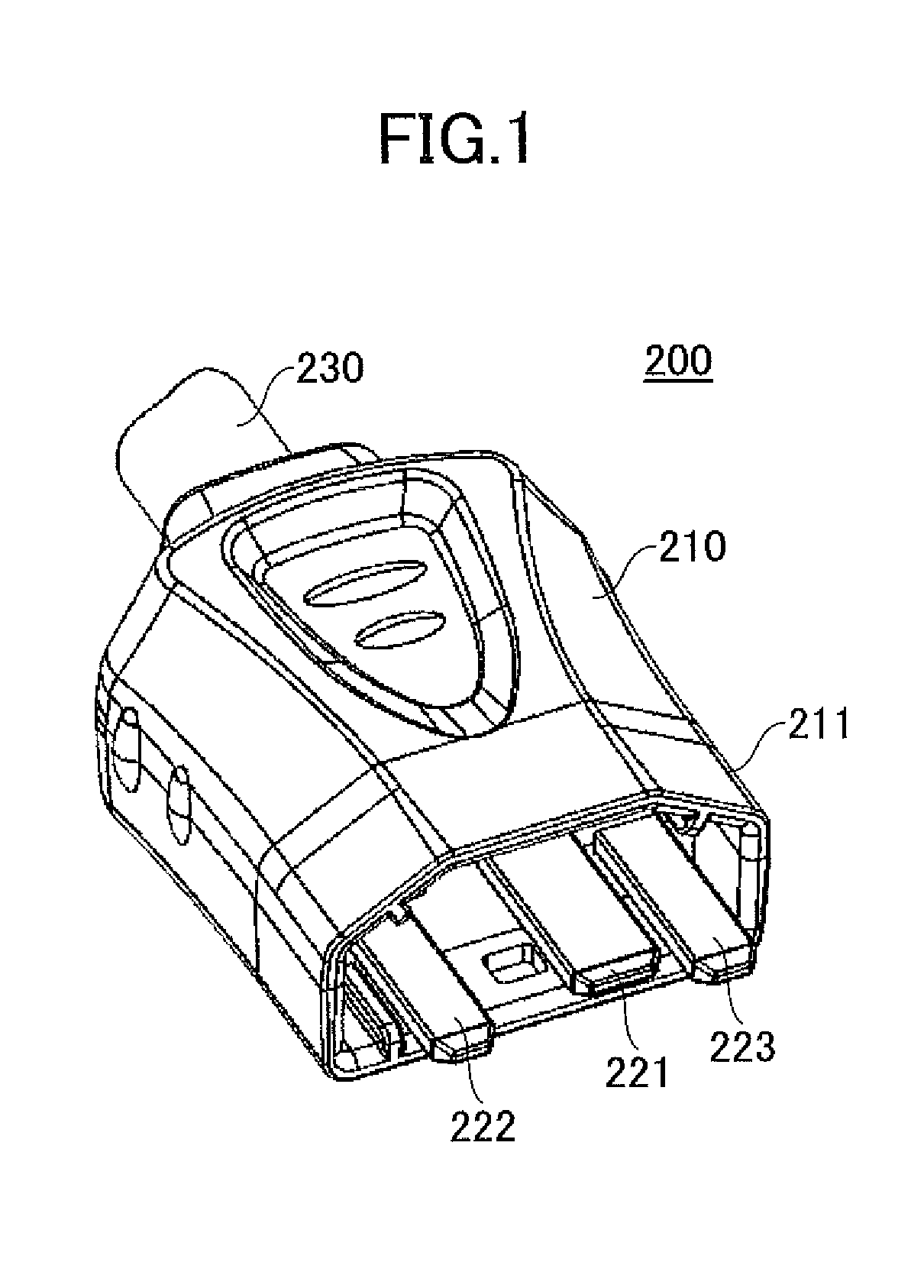
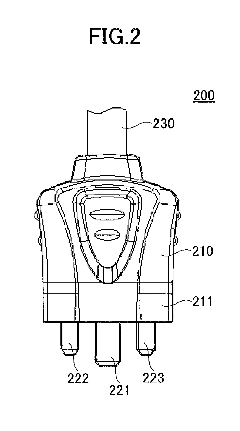
[0081]Firstly, referring to FIGS. 1 to 5, a plug connector 200 is explained. FIG. 1 is a perspective view of the plug connector 200. FIG. 2 is a plan view of the plug connector 200. FIG. 3 is a side view of the plug connector 200. FIG. 4 is a bottom view of the plug connector 200. FIG. 5 is a front view of the plug connector 200. The plug connector 200 includes a cover portion 210 formed by insulating material or the like and three plug terminals 221, 222, and 223, which are examples of ot...

second embodiment

[0107]Next, a switch of a second embodiment is described. The switch of the second embodiment corresponds to the switch portion of the first embodiment. The switch is described in more detail.

[0108]A power source switch used in a case where the voltage supplied from an electric power source is 100 V or greater.

[0109]When the voltage supplied from the electric power source is 100 V or greater, e.g., direct current 400 V, a commercially available switch may not shut down electric power supply. This phenomenon may be caused when contacting contacts are molten by heat caused by any reason because the voltage is high or the direct current is used. If such a phenomenon is caused, the function as the switch is completely lost to influence the electric power supply. Therefore, there occurs a problem in the function of the switch.

(Switch)

[0110]Next, an example of the switch of the second embodiment is described. The switch of the second embodiment is used to control supply of electric power....

third embodiment

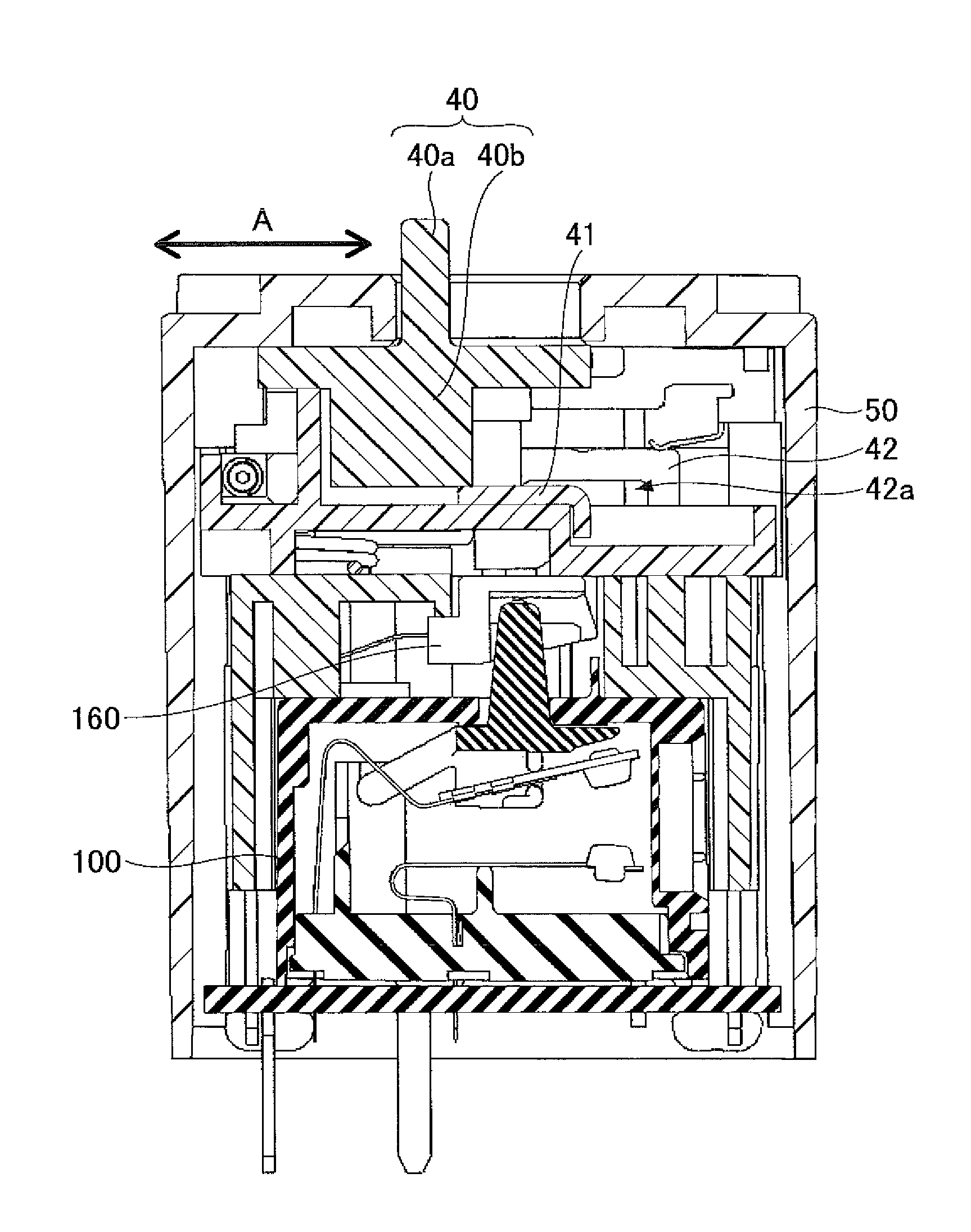
[0128]Next, a switch of a third embodiment is described. In the switch of the third embodiment, the turn-off state is illustrated in FIG. 40 and the turn-on state is illustrated in FIG. 41.

[0129]Referring to FIGS. 40 and 41, the switch of the third embodiment includes a card 340 having no rotating shaft. By pushing the button 160, the card 340 moves up or down to causing the fixed contact 111 of the fixed portion 110 to contact the movable contact 121 of the movable portion 120.

[0130]Specifically, by pressing the button 160, a contact portion 344a in contact with the button inner portion 161 of the button 160 is pushed. Thus, the card 340 moves downwardly. Then, an upper contact part 341 pushes the movable plate 122 downwardly to make the fixed contact 111 contact the movable contact 121. Thus, as illustrated in FIG. 41, the switch becomes the turn-on state. Under this state, in a manner similar to the second embodiment, a turn-on state retaining mechanism or the like (not illustrat...


PUM


Abstract

A connector includes a terminal to be connected to a terminal of another connector, a fixed contact, a movable contact provided on one end of a movable plate, a card being in contact with the movable plate, a slide portion, a button that contacts with the card and is pushed down according to a movement of the slide portion, and a spring connected to the button and generates force in a direction of separating a contact between the fixed contact and the movable contact. One of the fixed contact and the movable contact is connected to the terminal. The button is pushed down and the card moves to move the movable plate to cause the movable contact to contact with the fixed contact when the slide portion moves in one direction, and the movable contact is separated from the fixed contact when the slide portion moves in another direction.

Description

TECHNICAL FIELD[0001]The present invention relates to a connector and a switch.BACKGROUND ART[0002]Generally, an electric apparatus is activated by electric power supplied from an electric power source. Ordinarily, the electric power is supplied to the electric apparatus from the power source via a connector. As disclosed in Patent Documents 1 and 2, for example, such connector enables an electrical connection in a manner that a male type connector in a convex shape is engaged with a female type connector in a concave shape.[0003]Meanwhile, as a countermeasure against global warming or the like in recent years, a high voltage and direct current electric power supply is reviewed because power loss is small in voltage conversion, electric power transmission, or the like. Especially, such direct current power supply may be desirable in an information apparatus such as a server since the information apparatus may consume great electric power.[0004]As to the electric power supplied to th...

Claims


Application Information

Patent Timeline
Patent Type & Authority Patents(United States)
IPC IPC(8): H01H25/00H01H13/14H01R13/70H01H9/02H01H15/16H01R24/78H01R103/00
CPCH01R13/70H01H13/14H01R2103/00H01H15/16H01R24/78H01H9/0264
Inventor IWAMOTO, DAIEIBEAK, SEUNGSEOKYUBA, TAKASHIKIRYU, KOICHIHIROSE, KEIICHINORITAKE, MASATOSHI
Owner NTT FACILITIES INC
Why Eureka
Try Eureka