Systems and methods for optical isolation in measuring physiological parameters

a physiological parameter and optical isolation technology, applied in the field of non-invasive electrooptical technology for sensing and measuring physiological parameters, can solve the problems of unwarranted increase in electrical design requirements and/or serious affecting monitoring accuracy and power requirements, and achieve the effect of facilitating accurate and reliable monitoring of on

Active Publication Date: 2016-01-05
BEIJING SHUNYUAN KAIHUA TECH LTD
View PDF13 Cites 75 Cited by
  • Summary
  • Abstract
  • Description
  • Claims
  • Application Information

AI Technical Summary

Benefits of technology

[0010]In another aspect, the light source(s) and photo detector(s) may be positioned by and mounted to a printed circuit board. In one embodiment, the printed circuit board may be installed in the interior of the monitor and the lenses may be maintained in the monitor caseback. Portions of the caseback may extend outward to contact the printed circuit in a region between the one or more light sources and the one or more photo detectors to prevent light emitted by the light sources from being directly detected by the photo detectors. In some embodiments, these outwardly extending portions of the caseback may be barrier walls that optically isolate the one or more LEDs from the one or more photo detectors. Such a configuration may ensure that light detected by the one or more photo detectors is light that has been reflected by a user's tissue rather than light emitted directly from the one or more light sources (whether that light has traveled across the user's tissue or across the printed circuit). In embodiments in which the lenses comprise an epoxy layer poured over the one or more light sources and / or photo detectors, the barrier walls may also serve as forms for accepting the liquid, semi-liquid, or gel-like epoxy. Such forms may dictate the shape of the solidified lenses and / or prevent the liquid, semi-liquid, or gel-like epoxy from spilling into other portions of the caseback or monitoring device.
[0011]In further embodiments, a pliant opaque layer of tape or sponge-like material may be positioned on the printed circuit board such that the outwardly extending portions of the caseback and / or barrier walls may contact the opaque layer to further ensure optical isolation of the light sources and photo detectors. In particular, the opaque layer may further prevent light emitted from the one or more light sources from traveling along the surface of the printed circuit board and reaching the one or more photo detectors without first traveling into the user's tissue and being reflected back to the one or more photo detectors.

Problems solved by technology

Otherwise, the photo detector will receive optical energy that is not modulated by a user's heartbeat, which can result in an unwarranted increase in electrical design requirements and / or seriously affect monitoring accuracy and power requirements.

Method used


Image

  • Systems and methods for optical isolation in measuring physiological parameters
  • Systems and methods for optical isolation in measuring physiological parameters
  • Systems and methods for optical isolation in measuring physiological parameters

Examples


Embodiment Construction

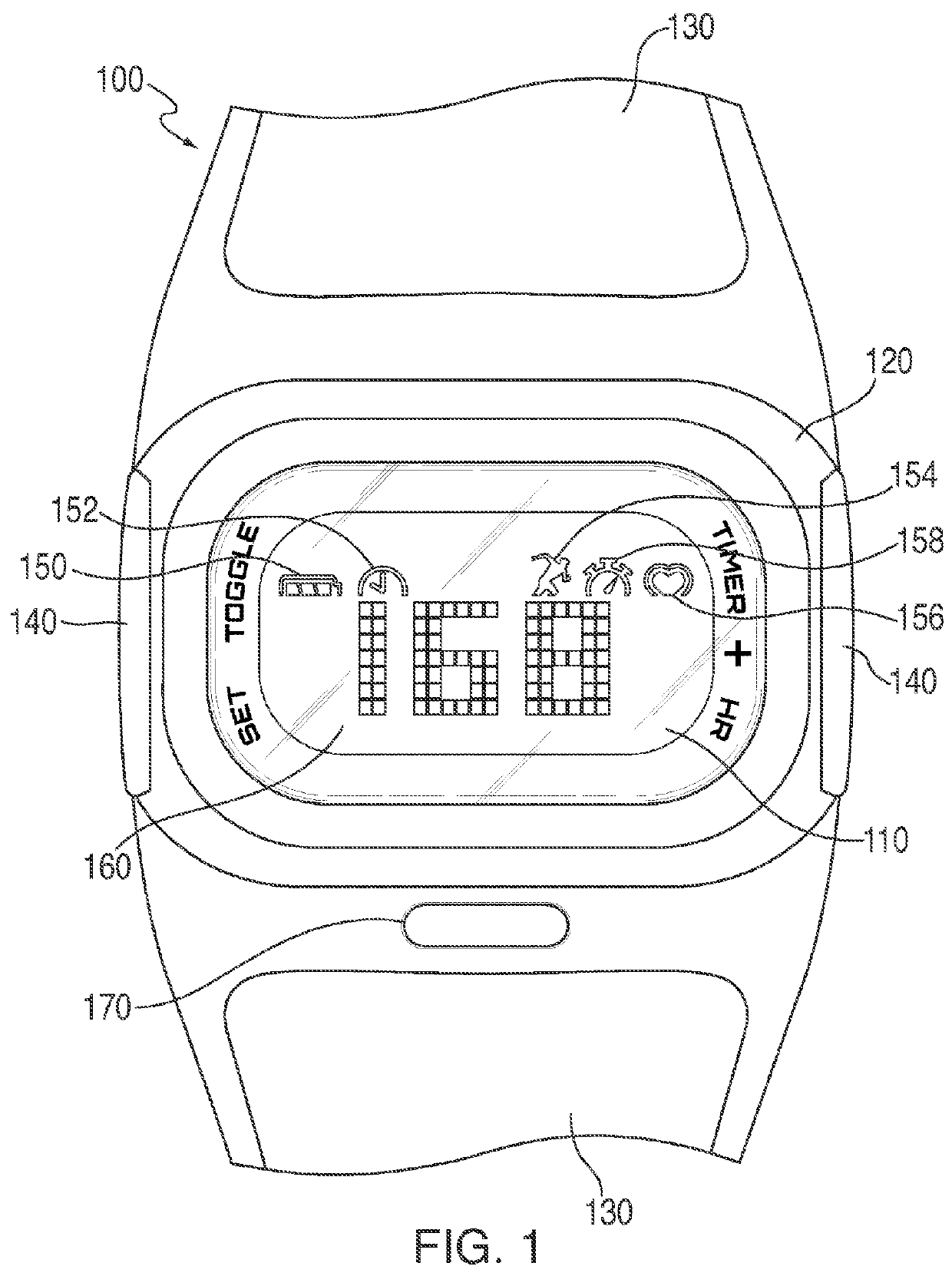
[0029]Disclosed herein are embodiments of an apparatus for sensing, measuring, and displaying physiological information. In one aspect, the apparatus may comprise an optical sensor incorporated into a wearable device. The optical sensor may be incorporated at a location of the wearable device such that, in use, a surface of the optical sensor may be adjacent or in close proximity to a targeted area of a user's body. In one embodiment, the optical sensor may comprise one or more light sources for emitting light proximate the targeted area and one or more optical detectors for detecting reflected light from the targeted area.

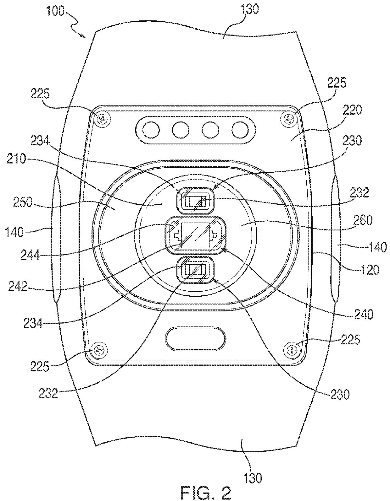
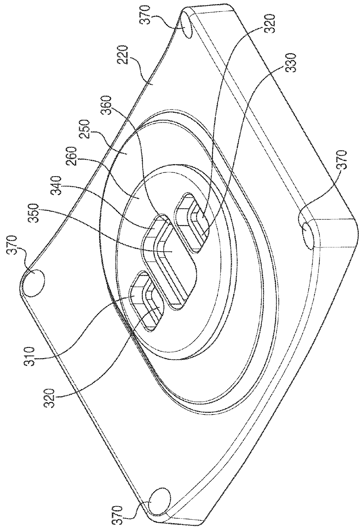
[0030]In another aspect, the optical sensor may be incorporated into the wearable device such that at least a portion of the optical sensor may protrude or extend beyond at least a portion of a device housing. In some embodiments, a height which the portion of the optical sensor may extend beyond the device housing may be fixed. In alternative embodiments, the hei...


PUM


Abstract

Described herein are systems and methods for optically isolating components of an optical sensor in physiological monitoring devices worn by a user to sense, measure, and / or display physiological information. An optical sensor may be mounted in the rear face of the device, emit light proximate a targeted area of a user's body, and detect light reflected from the targeted area. Optically isolating structure may be located at least partially between one or more components of the optical sensor to ensure that light detected by the sensor is light reflected from the targeted area rather than light emitted directly from a light source and / or ambient light. The optically isolating structure may, in some cases, extend between a contact surface of the monitoring device to a base portion of the sensor components or a surface of a circuit board to which the sensor components are mounted.

Description

[0001]This is a continuation-in-part application of U.S. patent application Ser. No. 14 / 468,916, filed Aug. 26, 2014, which claims the benefit of priority to U.S. Provisional Patent Application No. 61 / 976,388, filed Apr. 7, 2014, both of which are expressly incorporated herein by reference.FIELD OF THE DISCLOSURE[0002]The embodiments relate generally to systems and methods that use non-invasive electro-optical technology for sensing and measuring physiological parameters and, more specifically, systems and methods for optically isolating light reflected from a user's tissue from light emitted directly from a light source during the sensing and / or measuring physiological parameters.BACKGROUND[0003]Many portable devices have been developed in which optical sensors are used to detect variation in blood flow through arteries or blood volume in subcutaneous tissue. Applications include the monitoring of heart rate, glucose level, apnea, respiratory stress, and other physiological conditi...

Claims


Application Information

Patent Timeline
Patent Type & Authority Patents(United States)
IPC IPC(8): A61B5/00A61B5/021A61B5/024
CPCA61B5/0059A61B5/02141A61B5/02438A61B5/6824A61B5/02427A61B5/6802A61B5/7203A61B5/681A61B2560/0462A61B2562/0233A61B5/6843A61B2562/185
Inventor FEI, MING, SHUN
Owner BEIJING SHUNYUAN KAIHUA TECH LTD
Why Eureka
Try Eureka