Transform mechanism of a finishing wheel for an abrasive belt polishing finisher

a technology of polishing finisher and polishing wheel, which is applied in the field of mechanical technology, can solve the problems of poor polishing and finishing efficiency, labor intensive and time-consuming, and inability to completely process the desired curved surface using the conventional plane abrasive belt, and achieves fast and precise control, high-quality polishing, and reliable switching

Active Publication Date: 2016-01-26
TAIZHOU FEDERAL ROBOT TECH
View PDF7 Cites 0 Cited by
  • Summary
  • Abstract
  • Description
  • Claims
  • Application Information

AI Technical Summary

Benefits of technology

[0020]Compared with the prior art, the surface of the work piece could be processed with curved surfaces with different curvatures by high-quality polishing and finishing treatment by using the transform mechanism of the finishing wheel for the abrasive belt polishing finisher. The transform mechanism could be widely applied. As each of the finishing wheels has its own driving element, the finishing wheels can be more quickly and precisely controlled. Each of the finishing wheels will not influence each other and could be switched more reliably.

Problems solved by technology

However, with respect to work pieces having a number of complicated curved surfaces, for example, water taps, the desired curved surfaces could not be completely processed by using the conventional plane abrasive belts.
The special curved surfaces on the surface of the work piece are conventionally polished and finished by the operators, which is not only labor intensive and time and labor consuming, but also has a very poor polishing and finishing efficiency.
Moreover, the polishing and finishing precision of the surface of the work piece is not enough.

Method used


Image

  • Transform mechanism of a finishing wheel for an abrasive belt polishing finisher
  • Transform mechanism of a finishing wheel for an abrasive belt polishing finisher
  • Transform mechanism of a finishing wheel for an abrasive belt polishing finisher

Examples


first embodiment

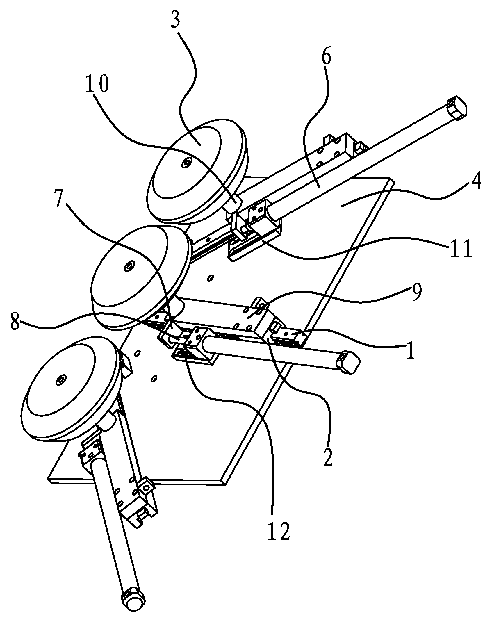
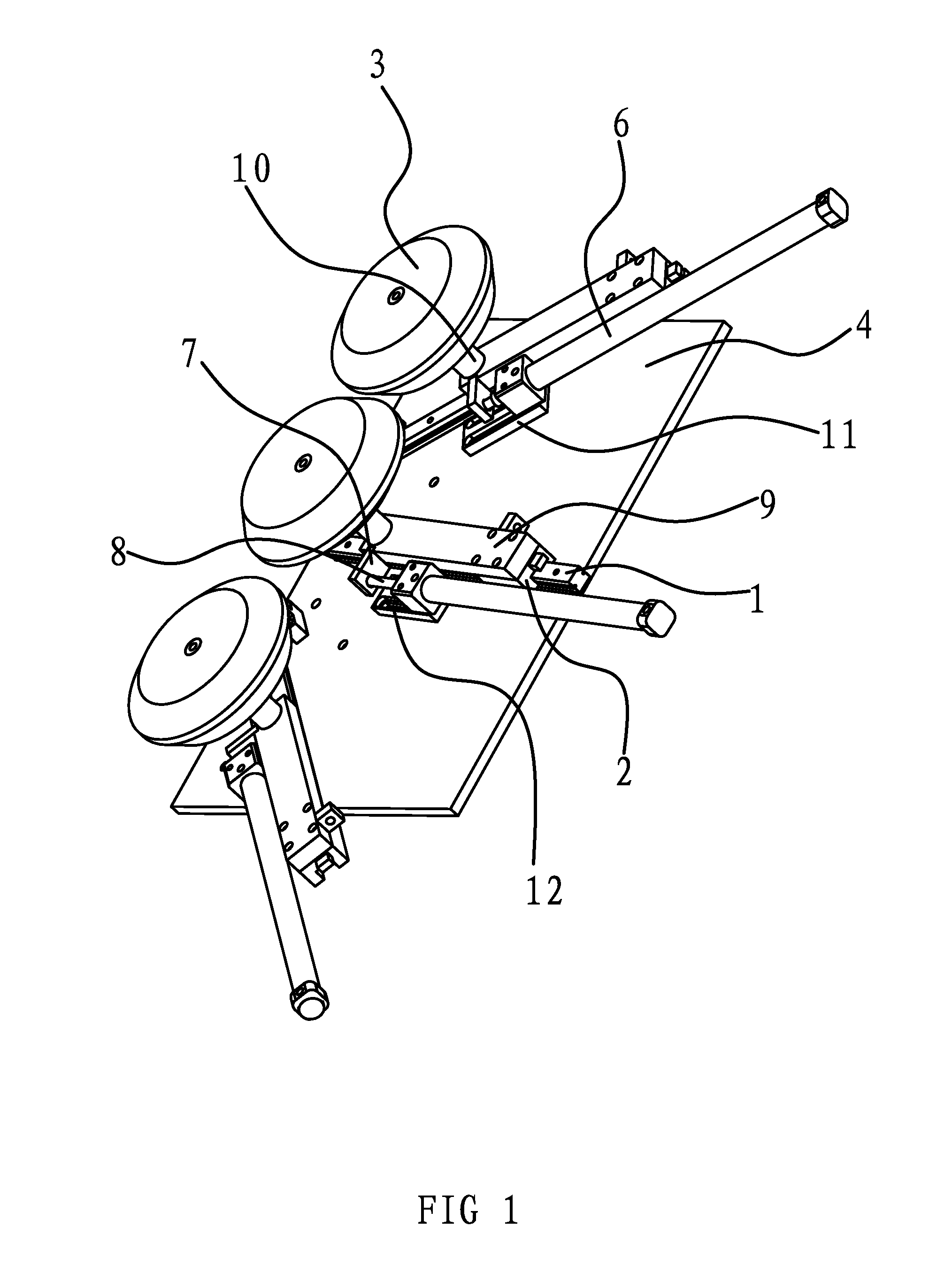
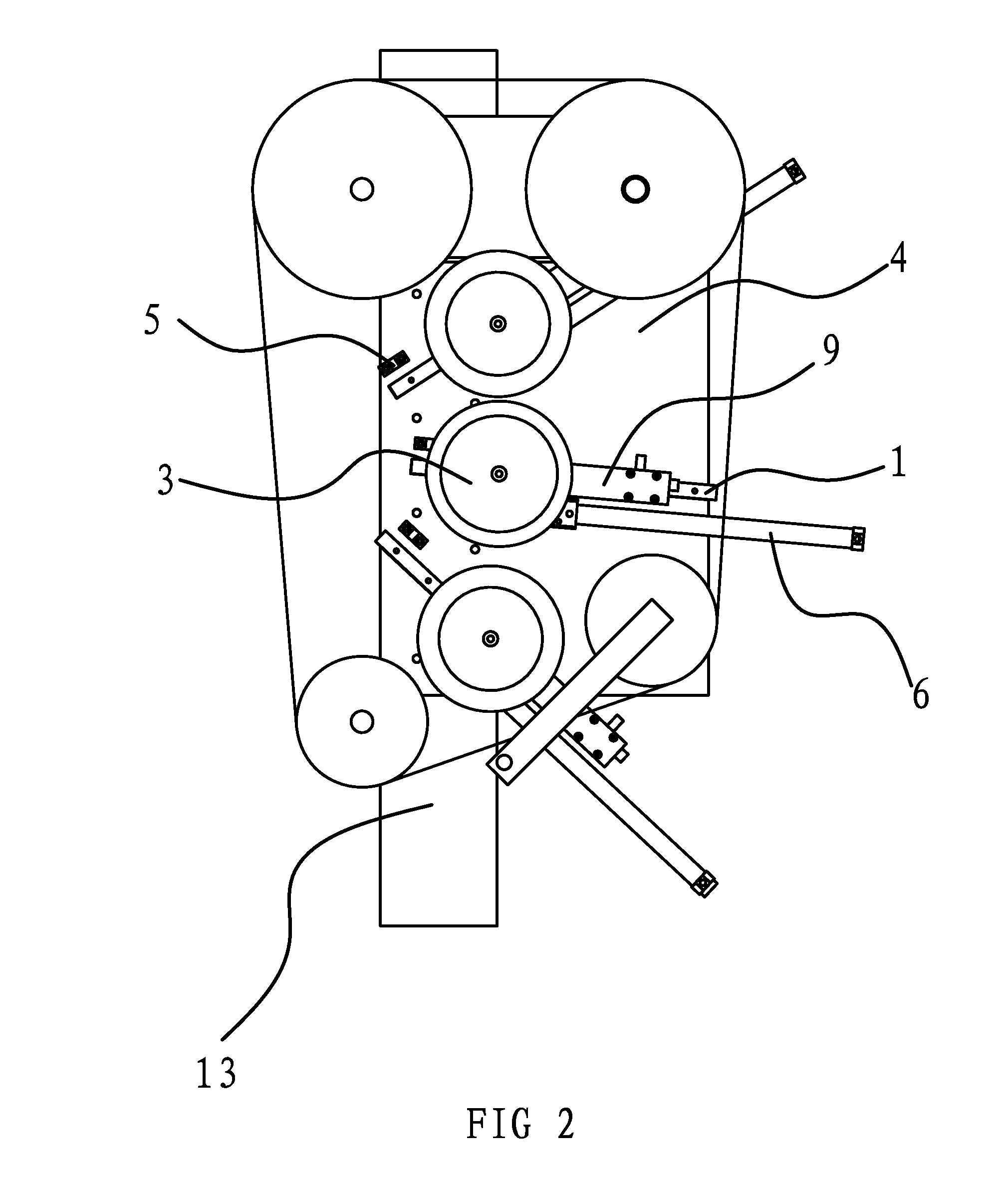
[0027]As shown in FIGS. 1-3, a transform mechanism of a finishing wheel for an abrasive belt polishing finisher is provided on the inner side of the abrasive belt of the finisher. The transform mechanism comprises three slide rails 1 disposed on the side of frame 13 of the finisher and sliders 2 on the slide rails 1. The side of the frame 13 of the finisher is fixedly connected with a mounting plate 4. Mounting grooves having a shape matched with the slide rails 1 are formed on the mounting plate 4. The slide rails 1 are fixed into the mounting grooves.

[0028]Each of the sliders 2 on three slide rails 1 is connected with a finishing wheel 3. The curved surfaces on the rim of the three finishing wheels 3 have different curvatures. A driving element connected with the slider 2 is located on the frame 13 of the finisher close to each slider 2. The driving element could be an air cylinder and a solenoid valve 5. The solenoid valves 5 are fixed on the mounting plate 4 to which slide plate...

second embodiment

[0034]The structure and principle of the transform mechanism of a finishing wheel for an abrasive belt polishing finisher according to this embodiment are substantially the same as those of the first embodiment except that, the driving element in this embodiment is embodied as an oil cylinder and a solenoid valve 5, in which both the oil cylinder body 6 and the solenoid valve 5 are fixed on the mounting plate 4. A plate-like connection part 7 is projected from the side of the positioning block 9. The end of the piston rod 8 of the oil cylinder is vertically fixedly connected with the plate-like connection part 7. The operation of the oil cylinder is the same as that of the air cylinder.

third embodiment

[0035]The structure and principle of the transform mechanism of a finishing wheel for an abrasive belt polishing finisher according to this embodiment are substantially the same as those of the first embodiment except that, the driving element in this embodiment is embodied as a motor and a lead screw, in which the motor is fixed on the mounting plate 4 and one end of the rotation shaft of the motor is connected with one end of the lead screw. The rotation shaft of the corresponding motor is controlled by program into rotation, and the lead screw is driven into rotation by the rotation shaft of the motor. As the lead screw is connected to the inner side of the slider 2, the rotation of the lead screw could be turned into axial movement of the slider 2, so that the corresponding finishing wheel 3 could move forward and be pressed against the inner side of the abrasive belt.

[0036]The embodiments described herein are merely illustrative of the spirit of the invention. It is obvious for...


PUM


Abstract

The invention discloses a transform mechanism of a finishing wheel for an abrasive belt polishing finisher in the field of mechanical technology. The invention is disposed on the inner side of the abrasive belt of the finisher, comprising several slide rails disposed on the side of the frame of the finisher and sliders on the slide rails. A finishing wheel is fixedly connected with each of the sliders. The curved surface of the rim of each of the said finishing wheels has a different curvature. A driving element connected with the slider is provided on the frame of the finisher close to each of the sliders. The finishing wheel corresponding to the driving element, driven by the said driving element, is pressed against the inner side of the abrasive belt. The transform mechanism of the invention could be widely applied and has a high polishing and finishing efficiency.

Description

BACKGROUND OF THE INVENTION[0001]1. Field of Invention[0002]The present invention pertains to the field of mechanical technology. The invention relates to a finishing wheel for an abrasive belt polishing finisher, and particularly to a transform mechanism of a finishing wheel for an abrasive belt polishing finisher.[0003]2. Related Art[0004]The abrasive belt polishing finisher is one of the polishing finishers, and is an ordinary mechanical processing device for polishing and finishing the surface of the work piece. The abrasive belt polishing finisher has been widely applied in hardware and plumbing industries. The surface of the work piece is polished and finished by contacting the surface of the work piece with the abrasive belt and using the grinding performance of the abrasive particles on the abrasive belt in the abrasive belt polishing finisher. The quality and precision of the surface of the work piece are good upon abrasive belt polishing and finishing.[0005]The existing th...

Claims


Application Information

Patent Timeline
Patent Type & Authority Patents(United States)
IPC IPC(8): B24B21/14B24B21/16B24B21/18B24B41/02B24B21/20B24B21/12
CPCB24B21/14B24B21/12B24B21/16B24B21/18B24B21/20B24B41/02
Inventor CHEN, QIYUE
Owner TAIZHOU FEDERAL ROBOT TECH
Why Eureka
Try Eureka