
Cam engine

a cam engine and cam profile technology, applied in the direction of positive displacement liquid engines, piston pumps, machines/engines, etc., can solve the problem of reducing the possibility of breaking the contact between the main roller and the cam profile corresponding to the cam, and achieve the effect of improving the functional reliability of the apparatus

Active Publication Date: 2016-01-26
BAHNEV BOYAN
View PDF11 Cites 0 Cited by
  • Summary
  • Abstract
  • Description
  • Claims
  • Application Information

AI Technical Summary

Benefits of technology

[0009]The problem solved by the present invention is to provide technical solutions that improve the functional reliability of the apparatuses having a cam mechanism and in particular piston cam engines.
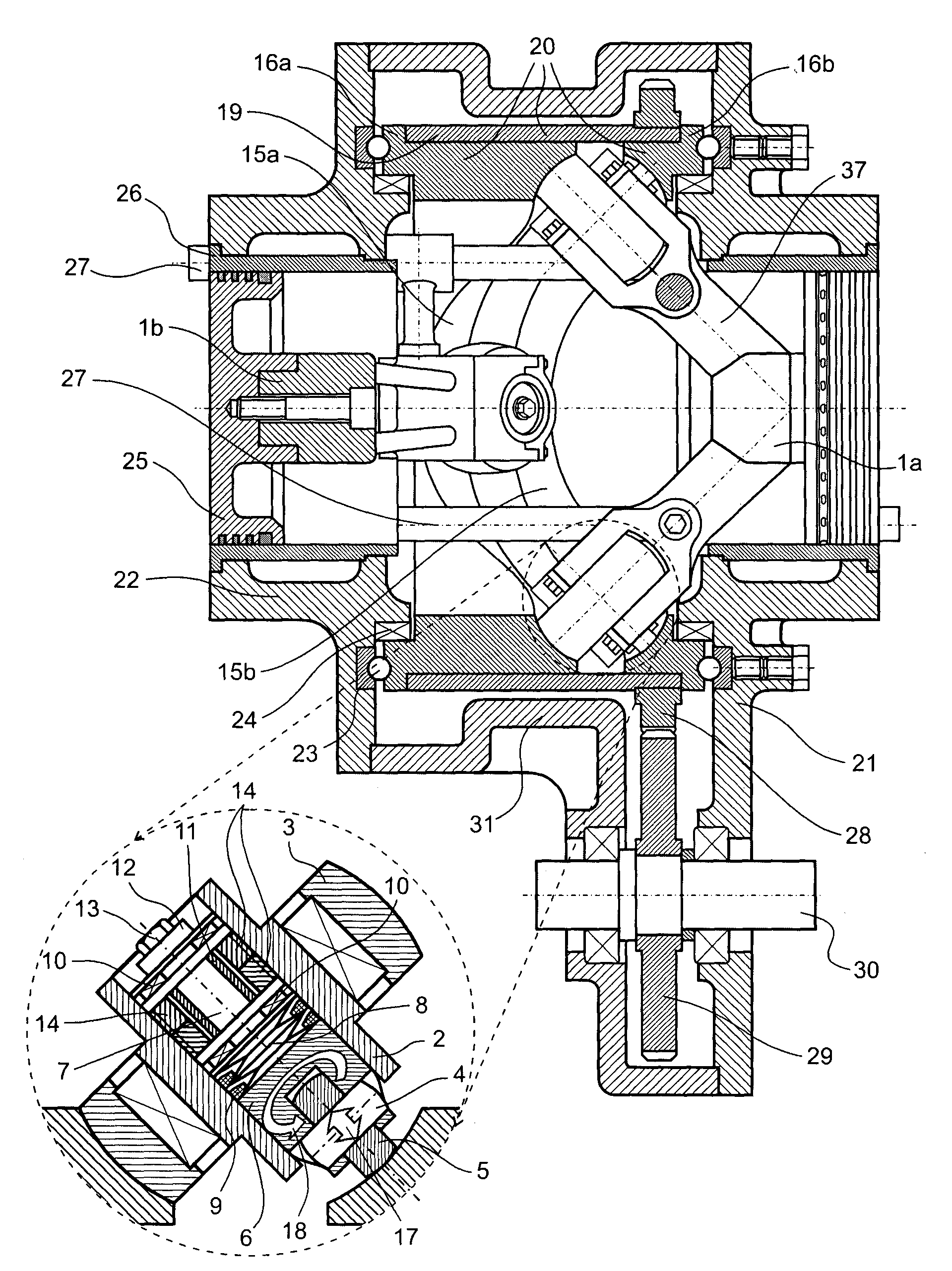
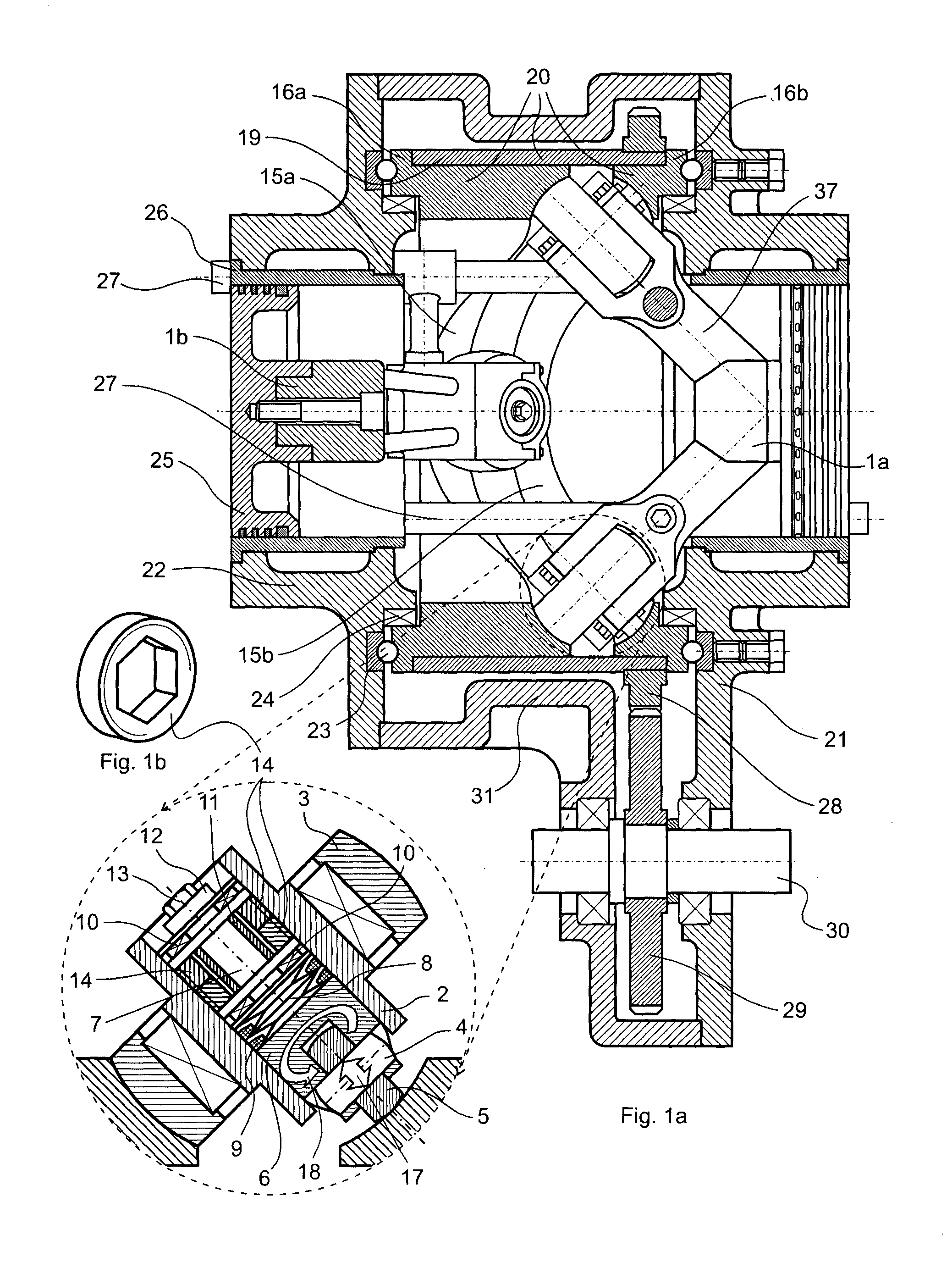
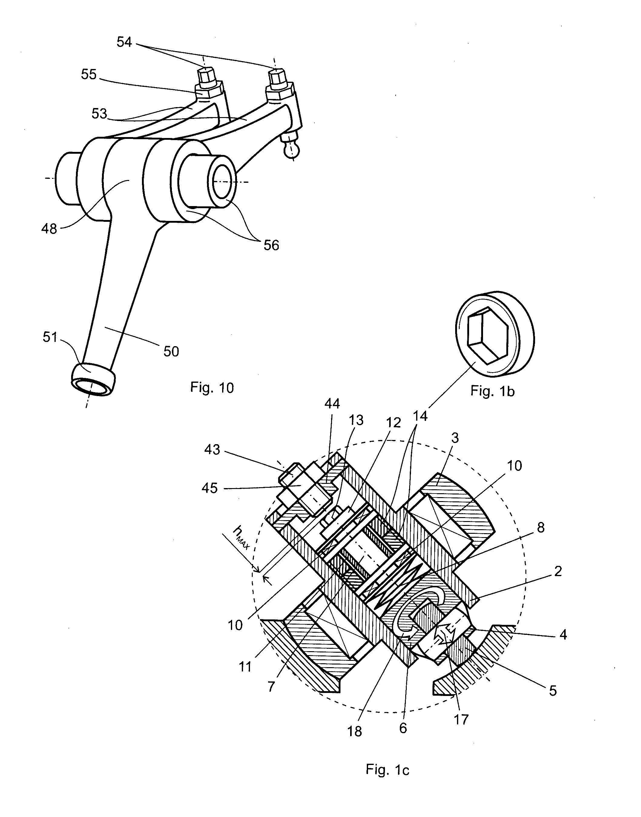
[0010]These and other problems are solved by a cam engine comprising a housing, at least one cylinder, at least one piston moving in the cylinder, cylindrical tubular 3D cam with a cam groove on the inner cylindrical surface, which groove is made so that the line forming its surface cross-section is a straight or concave line whose lower end is located at the axis of the 3D cam, and at least two asynchronously moving equal-mass followers, positioned against each other, at least one of which pistons is a working piston. Each follower comprises at least two arms, standing at an angle to each other and having main rollers bearing at the free ends of the corresponding arm, and each follower also comprises additional rollers that can move along the axes of the corresponding main rollers, so that each main and additional roller contacts the cam groove. Besides the additional rollers have the possibility to rotate in relation to the axes of their corresponding main rollers, so that they are able to self-adjust to achieve rolling without sliding. Thus, the additional rollers can move in parallel and rotate around the axes of their corresponding main rollers at the same time, whereat a rolling without sliding takes place. The additional rollers include stoppers for limiting their movement along the axes of the main rollers, which additionally reduces the possibility of breaking the contact between the main rollers and their corresponding cam profiles without the preloading of the elastic elements used being too high. Thus, the movement of the additional rollers is kept within acceptable limits. The cam groove is characterized with periodically changing cross-section, depending on the number of the convex and concave sections of the profile of the 3D cam. This reduces the linear movement of the additional rollers compared to the corresponding main rollers.
[0011]In one embodiment of the invention, the cam engine has a cam groove, which is made so that at the top and bottom dead centers the distance between the cam profiles of the groove of the 3D cam in the cross-section is the greatest, and the distance in the cross-section between the cam profiles of the groove of the 3D cam between the two dead centers is the smallest. This reduces to the maximum possible extent the movement of the additional rollers in comparison with the axes of their corresponding main rollers. When the cam groove is shrinking, the distance between the centers of the axes of each pair of main and additional rollers remains constant and therefore the relative movement between any additional roller and the corresponding main bearing journal is eliminated.

Problems solved by technology

The additional rollers include stoppers for limiting their movement along the axes of the main rollers, which additionally reduces the possibility of breaking the contact between the main rollers and their corresponding cam profiles without the preloading of the elastic elements used being too high.

Method used


Image

  • Cam engine
  • Cam engine
  • Cam engine

Examples


Embodiment Construction

[0050]According to the invention, different two- or one-piston cam engines can be realized, which execute different working cycles depending on the specific application of the engine that can function as a compressor, pump, internal combustion engine or a combination of the above-mentioned.

[0051]FIG. 1a and FIG. 1b show one embodiment of two-piston cam engine according to the invention. The engine comprises a tubular 3D cam 20, which is an assembly of cam bushings 16a and 16b and a tubular element 19 that orientates cam bushings 16a and 16b in such a way that their cam profiles 15a and 15b form a cam groove on the internal surface of the 3D cam 20. The engine comprises two identical followers 1a and 1b as well, each one of them having two arms 37. To the free ends of the arms 37, which in this case are shaped as bearing forks, main bearing journals 2 and main rollers 3 are mounted. The main bearing journals 2 are of tubular geometry and in their cylindrical cavities additional beari...


PUM


Abstract

The invention relates to a cam engine used in different field of the mechanical engineering, as internal-combustion engines, compressors, pumps etc. The cam engine comprises cylinders (26) with pistons (25), cylindrical tubular 3D cam (20) having a cam groove on the inner cylindrical surface and at least two asynchronously moving followers (1a and 1b) with arms (37) having main and additional rollers (3, 5).

Description

FIELD OF THE INVENTION[0001]The invention relates to a piston cam engine and particularly to an opposed-piston cam engine that may find application in different fields of mechanical engineering, e.g. internal combustion engines, compressors and etc. Engines, constructed according to this invention, could be used in various land, water and air vehicles, as well as in stationary aggregates.BACKGROUND OF THE INVENTION[0002]One of the common problems of the cam mechanisms is the relatively more rapid wear in comparison to the mechanisms which links are connected by hinged joints.[0003]The main reasons for the intensive wear of cam mechanisms are friction between the cam surface and the element, which is in contact with it; greater contact force transmitted by a very small area between the cam profile and the element in contact with the cam; as well as a break of contact between the cam and the element contacting with its profile and subsequent impact recovery of the contact between them...

Claims


Application Information

Patent Timeline
Patent Type & Authority Patents(United States)
IPC IPC(8): F01B13/04F04B9/04F01B3/04F01B9/06F02B75/02F02B57/00F02B75/26F02B57/08
CPCF04B9/042F01B3/045F01B9/06F02B75/26F01B13/045F02B57/00F02B57/08F02B75/265F02B2075/025
Inventor BAHNEV, BOYAN
Owner BAHNEV BOYAN
Learn More