Hinge module and foldable device

a technology of hinge module and folding device, which is applied in the field of folding device, can solve the problems of shortening the life of the hinge module, and achieve the effects of increasing the torsion of the rotation, facilitating the rotation, and increasing the rotational friction

Active Publication Date: 2016-01-26
WISTRON CORP
View PDF13 Cites 5 Cited by
  • Summary
  • Abstract
  • Description
  • Claims
  • Application Information

AI Technical Summary

Benefits of technology

[0010]The invention provides a foldable device including a first body, a second body and a hinge module. A hinge module is adapted to be disposed between the first body and the second body to facilitate in rotating the second body relative to the first body. The hinge module includes a shaft, a first bracket, a second bracket, an electromagnet and a magnetic element. The first bracket is adapted to be fixed on the first body to fix a shaft. The second bracket is adapted to be fixed on the second body and passed through by the shaft, so that the second bracket is capable of being rotated relative to the first bracket. The electromagnet is directly or indirectly installed on the shaft. The magnetic element is directly or indirectly installed on the shaft, and capable of being attracted or repelled with the electromagnet under the magnetic force of the electromagnet. At least one of the electromagnet and the magnetic element is capable of being moved axially along the shaft but substantially incapable of being rotated with the shaft as an axis, such that when the electromagnet is activated by power, at least one of the electromagnet and the magnetic element is capable of being moved axially to a first position and to press the second bracket to increase a rotational friction, thereby increasing a torsion of a rotation of the second bracket relative to the first bracket.

Problems solved by technology

Nevertheless, a wear behavior of the cam structure can shorten lifetime of the hinge module.

Method used


Image

  • Hinge module and foldable device
  • Hinge module and foldable device
  • Hinge module and foldable device

Examples


Embodiment Construction

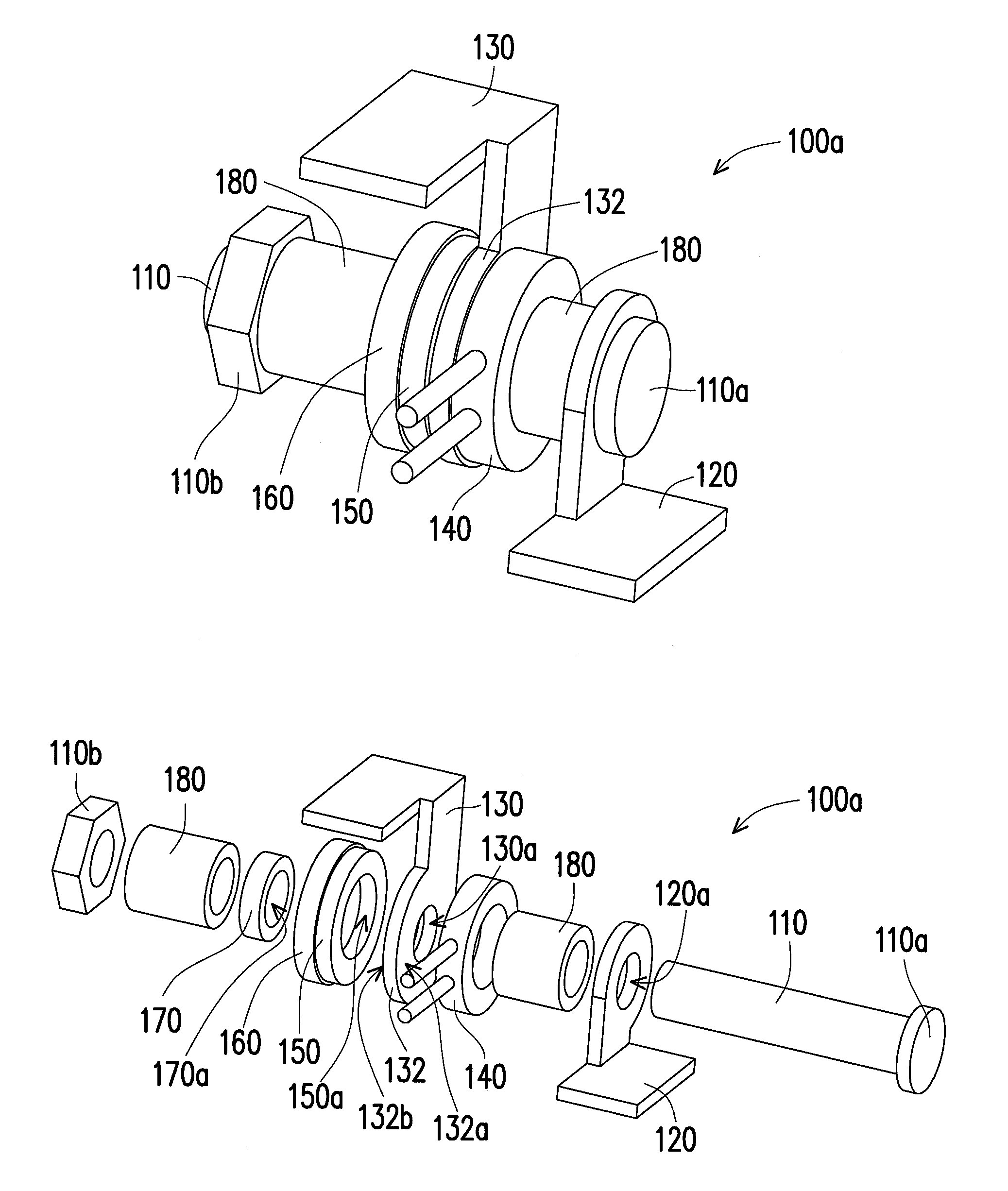
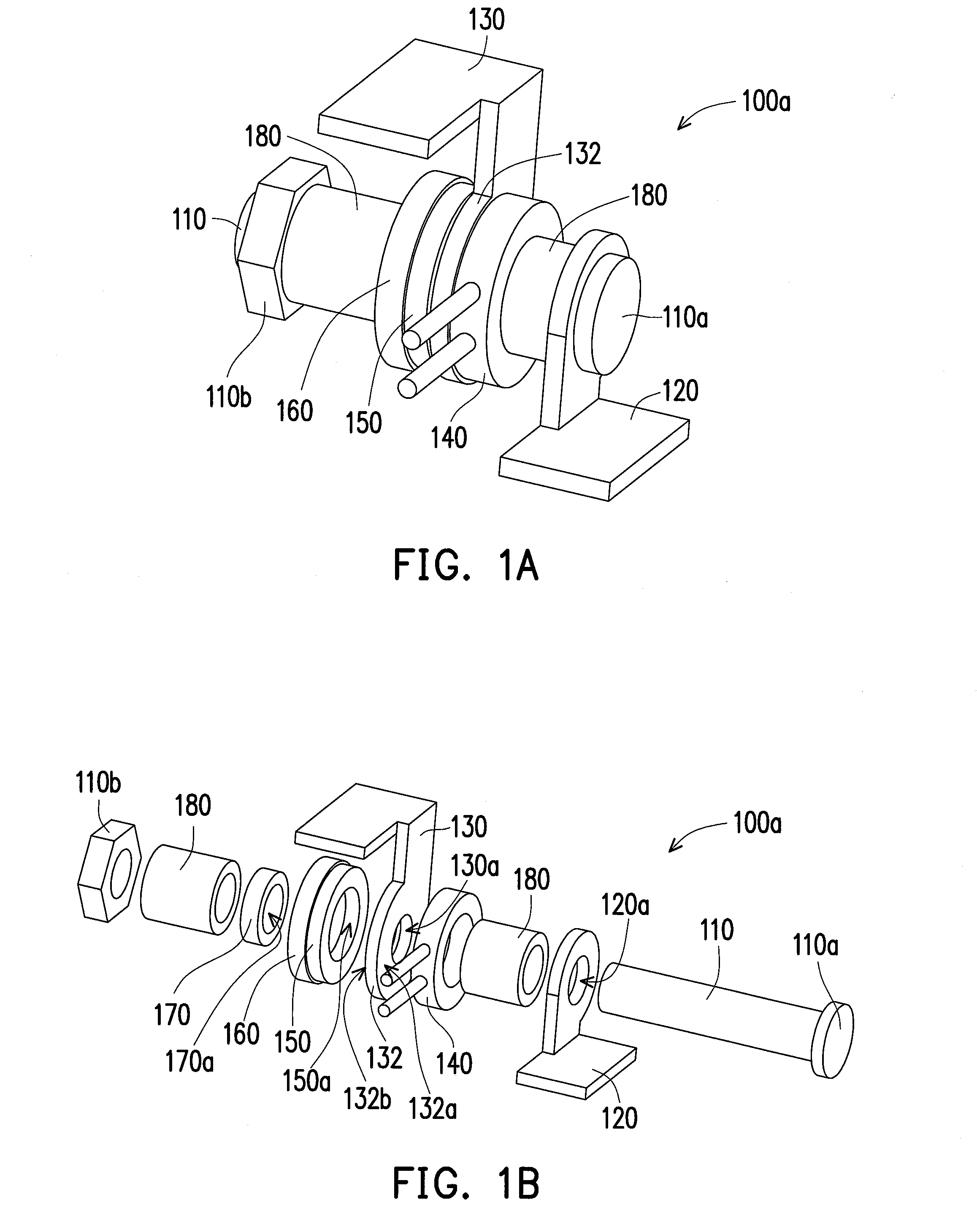
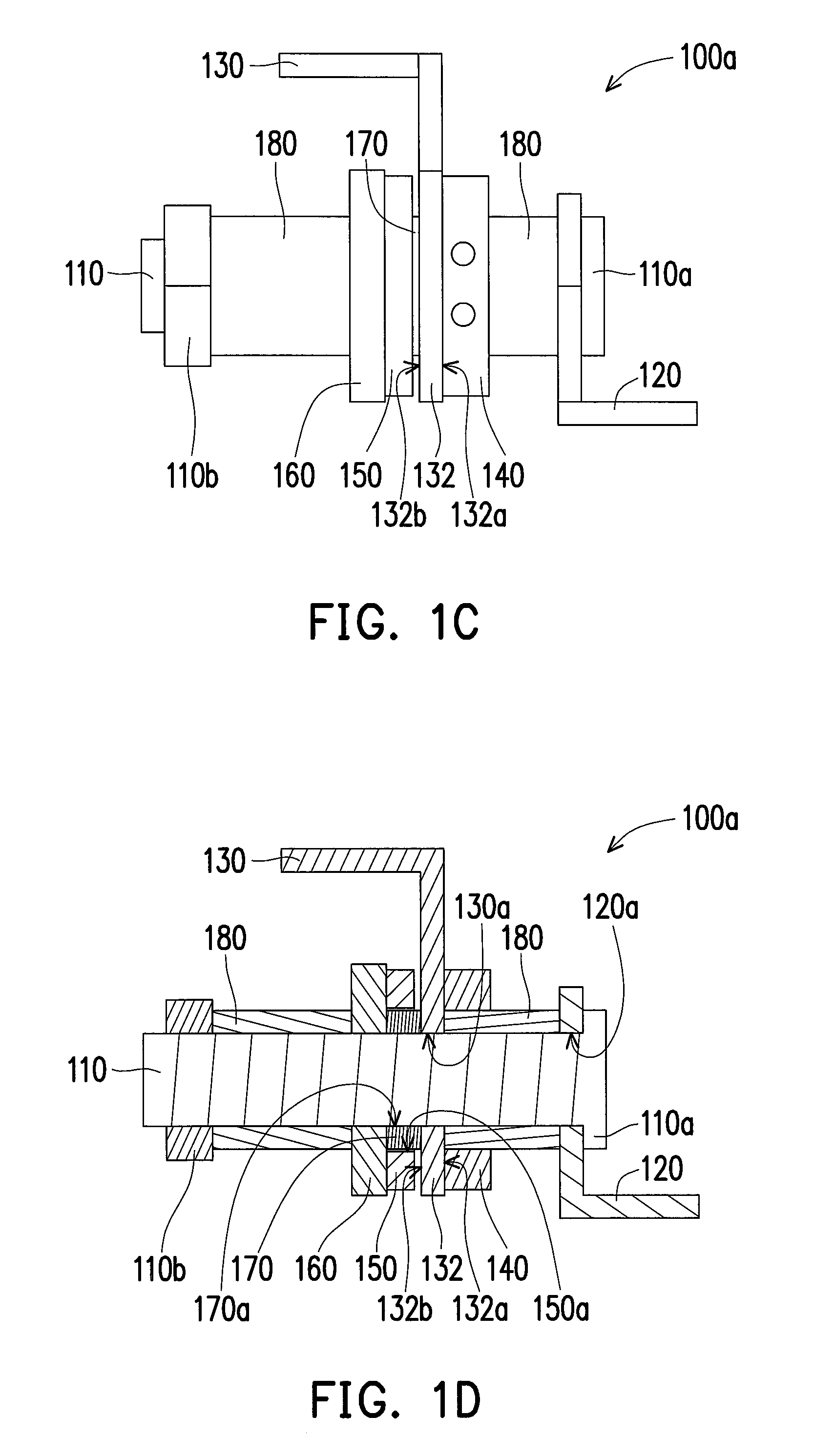
[0031]Referring to FIGS. 1A, 1B, 1C, 1D and 1F together, in the present embodiment, a hinge module 100a is adapted to be disposed between a first body 12 and a second body 14 in a foldable device 10. The first body 12 is, for example, a host base of a notebook computer, and the second body 14 is, for example, a display of the notebook computer. The hinge module 100a includes a shaft 110, a first bracket 120, a second bracket 130, an electromagnet 140 and a magnetic element 150. The first bracket 120 is fixed on the first body 12 and has a first shaft hole 120a to be passed through and fixed by the shaft 110. The second bracket 130 is fixed on the second body 14 and has a second shaft hole 130a to be pivotally passed through by the shaft 110, so that the second bracket 130 is capable of being rotated relative to the first bracket 120 with the shaft 110 as an axis. The second bracket 130 has a bearing 132 to be passed through by the shaft 110, and the bearing 132 includes a first late...


PUM


Abstract

A hinge module is disposed between a first body and a second body. A first bracket is fixed on the first body to fix a shaft. A second bracket is fixed on the second body and passed through by the shaft, so that the second bracket can be rotated relative to the first bracket. An electromagnet is installed on the shaft. A magnetic element is installed on the shaft, and capable of being attracted or repelled with the electromagnet. At least one of the electromagnet and the magnetic element is capable of being moved along the shaft axially but substantially incapable of being rotated with the shaft as an axis. When the electromagnet is activated, at least one of the electromagnet and the magnetic element is axially moved to press the second bracket to increase a torque of a rotation of the second bracket relative to the first bracket.

Description

CROSS-REFERENCE TO RELATED APPLICATION[0001]This application claims the priority benefit of Taiwan application serial no. 102123851, filed on Jul. 3, 2013. The entirety of the above-mentioned patent application is hereby incorporated by reference herein and made a part of this specification.BACKGROUND OF THE INVENTION[0002]1. Field of the Invention[0003]The invention relates to a foldable device and more particularly, to a hinge module and a foldable device.[0004]2. Description of Related Art[0005]Notebook computers have gradually replaced desktop computers and become a mainstream product in personal computers. A notebook computer usually includes a host base, and a display connected to a lateral side of the host base through a hinge module. When in use, the display can be flipped open relative to a side of the host base so as to output images for users, and the host base is provided with a keyboard and a touch pad for inputting commands to the host base.[0006]With advancements of t...

Claims


Application Information

Patent Timeline
Patent Type & Authority Patents(United States)
IPC IPC(8): E05D11/10G06F1/16
CPCG06F1/1681G06F1/1616G06F1/1679E05Y2900/606Y10T16/5401
Inventor TSAI, SHAO-HUAI
Owner WISTRON CORP
Why Eureka
Try Eureka