Surface roughness measuring unit and coordinate measuring apparatus

a technology of surface roughness and measuring unit, which is applied in the direction of mechanical diameter measurement, measurement device, instruments, etc., can solve the problems the contact pin unit inevitably oscillates in a direction, and it is unlikely that a determination can be made as to whether a measurement is made, so as to achieve the effect of lowering the measurement efficiency

Active Publication Date: 2016-02-02
MITUTOYO CORP
View PDF21 Cites 3 Cited by
  • Summary
  • Abstract
  • Description
  • Claims
  • Application Information

AI Technical Summary

Benefits of technology

[0009]When accuracy of processing on a work piece is measured, for example, surface roughness of the work piece may need to be measured in addition to a three-dimensional contour shape of the work piece. When both a contour shape and surface texture of the work piece are measured, until now, the contour shape of the work piece has been measured with a coordinate measuring apparatus, after which the work piece has been transferred from the coordinate measuring apparatus to a surface texture measuring device. Then, the surface roughness of the work piece surface has been measured with the surface texture measuring device. However, when such a transfer is required, more steps are involved, thereby drastically lowering measurement efficiency.

Problems solved by technology

However, when such a transfer is required, more steps are involved, thereby drastically lowering measurement efficiency.
However, when the contact pin unit is driven by the moving mechanism of the coordinate measuring device, the contact pin unit inevitably oscillates in a direction perpendicular to a direction in which the contact pin unit travels because of vibration from the active coordinate measuring.
In this case, considering resolution required to measure the surface roughness of the work piece, it is highly unlikely that a determination can be made as to whether a measurement result is surface roughness or an error due to the oscillation caused by the moving mechanism of the coordinate measuring device.
Thus, it is difficult to use the moving mechanism of the coordinate measuring device as a driver of the surface roughness measuring device.
However, even when the contact pin unit makes contact with a surface of the work piece, it is impossible to detect whether the contact pin unit has been properly set on the work piece surface, and thus the surface roughness cannot be properly measured.
Therefore, surface roughness cannot be measured simply by attaching the contact pin unit at the tip of the Z-spindle of the coordinate measuring device.

Method used


Image

  • Surface roughness measuring unit and coordinate measuring apparatus
  • Surface roughness measuring unit and coordinate measuring apparatus
  • Surface roughness measuring unit and coordinate measuring apparatus

Examples


first embodiment

[0035](First Embodiment)

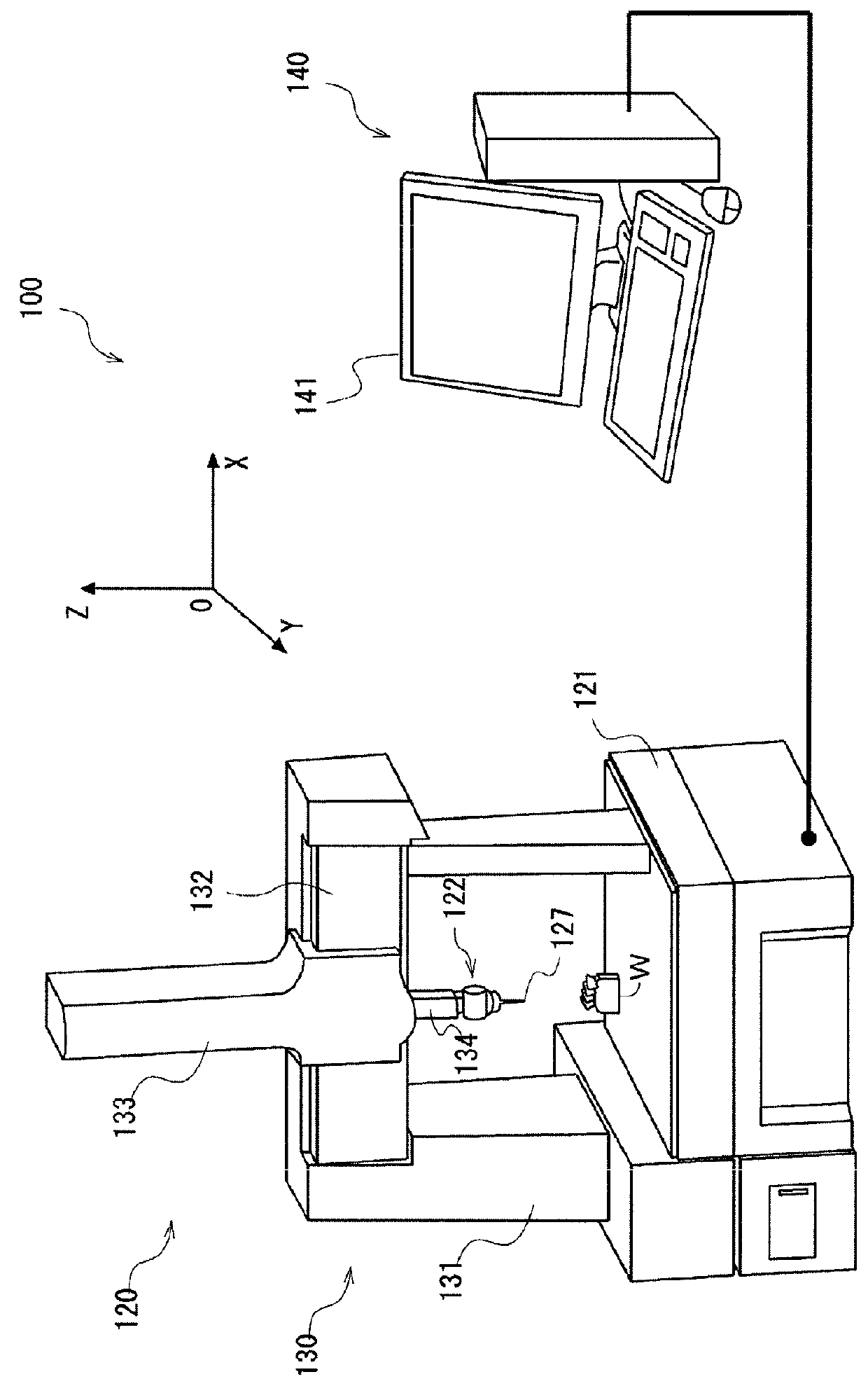
[0036]A surface roughness measuring unit according to a first embodiment of the present invention is described. The surface roughness measuring unit can be coupled to the moving mechanism 130 of the coordinate measuring system 100 and used instead of the touch sensor probe. In the following, embodiments of the present invention are described with reference to the drawings.

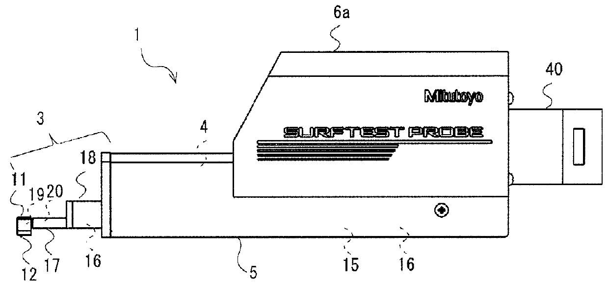
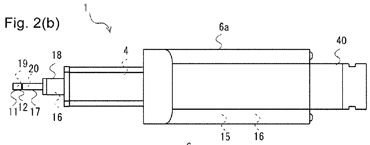
[0037]FIG. 2(a) is a side view of a surface roughness measuring unit 1. FIG. 2(b) is a top view of the surface roughness measuring unit 1. FIG. 2(c) is a front view of the surface roughness measuring unit 1.

[0038]The surface roughness measuring unit 1 includes a contact pin unit 3, a driver 4, a second supporter 6, and a joint 40. The surface roughness measuring unit 1 is coupled to the moving mechanism 130 (specifically, the bottom end of the Z-axis spindle) by the joint 40. (The second supporter 6 is connected to the joint 40 to link the contact pin unit 3 and the driver 4 to the joint 40....

second embodiment

[0058](Second Embodiment)

[0059]The surface roughness measuring unit 1 of the present invention further includes a collision detector 50 in addition to the contact detector described in the first embodiment. The collision detector 50 detects that the surface roughness measuring unit 1, rather than the skid 11, has collided with an unexpected obstacle.

[0060]The contact pin unit 3 of the surface roughness measuring unit 1 needs to perform highly precise parallel displacement. Thus, a positional relationship among the skid 11, the guide 26, and the driving mechanism 24 is restricted to some extent, and theretofore, it is unavoidably difficult to secure a sufficient gap between the bottom end surface of the skid 11 and the bottom surface of the driver casing 5. For example, as shown in FIGS. 2(a) to 2(c), the bottom end of the skid 11 and the bottom surface of the driver casing 5 are often approximately level with each other. Thus, in a case where unevenness or a projection is left on th...


PUM


Abstract

A surface roughness measuring unit according to the present invention includes a contact pin unit having a contact pin and a displacement detector, the contact pin being provided so as to project and retract through a through-hole of a skid and scanning and moving along a surface of a work piece, the displacement detector detecting displacement of the contact pin in a direction perpendicular to the work piece surface; a driver moving the contact pin unit forward and backward along the surface of the work piece; and a joint coupling the contact pin unit and the driver to a measurement head holder of a coordinate measuring system. The surface roughness measuring unit further includes a contact detector that detects contact of the skid on the surface of the work piece.

Description

CROSS-REFERENCE TO RELATED APPLICATIONS[0001]The present application claims priority under 35 U.S.C. §119 of Japanese Application No. 2012-230813, filed on Oct. 18, 2012, the disclosure of which is expressly incorporated by reference herein in its entirety.BACKGROUND OF THE INVENTION[0002]1. Field of the Invention[0003]The present invention relates to a surface roughness measuring unit and a coordinate measuring apparatus. More specifically, the present invention relates to a surface roughness measuring unit that can be attached to and used with a coordinate measuring apparatus.[0004]2. Description of Related Art[0005]A coordinate measuring apparatus is known for measuring a three-dimensional contour shape of a work piece (for example, Japanese Patent Laid-open Publication No. 2006-201105).[0006]The coordinate measuring apparatus includes a measurement head having at a tip of a stylus a contact ball that makes contact with a work piece, a moving mechanism moving the measurement head...

Claims


Application Information

Patent Timeline
Patent Type & Authority Patents(United States)
IPC IPC(8): G01B5/04G01B7/02G01B5/16G01B5/12G01B5/28G01B5/08B82Y35/00G01B5/004G01B5/008G01B5/012G01B5/016
CPCG01B5/012G01B5/016G01B5/28G01B7/023B82Y35/00G01B5/008
Inventor HIRANO, KOTAROHAMA, NOBUYUKIARAI, MASANORIMATSUMIYA, SADAYUKI
Owner MITUTOYO CORP
Why Eureka
Try Eureka