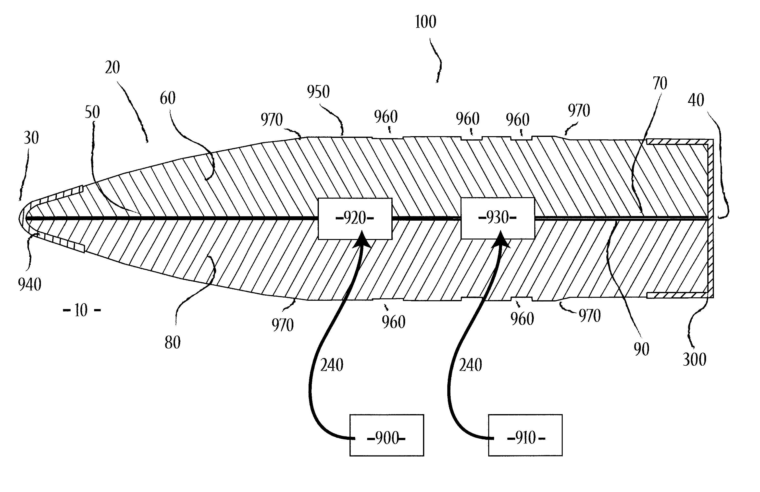
Longitudinally sectioned firearms projectiles
- Summary
- Abstract
- Description
- Claims
- Application Information
AI Technical Summary
Benefits of technology
Problems solved by technology
Method used
Image
Examples
first embodiment
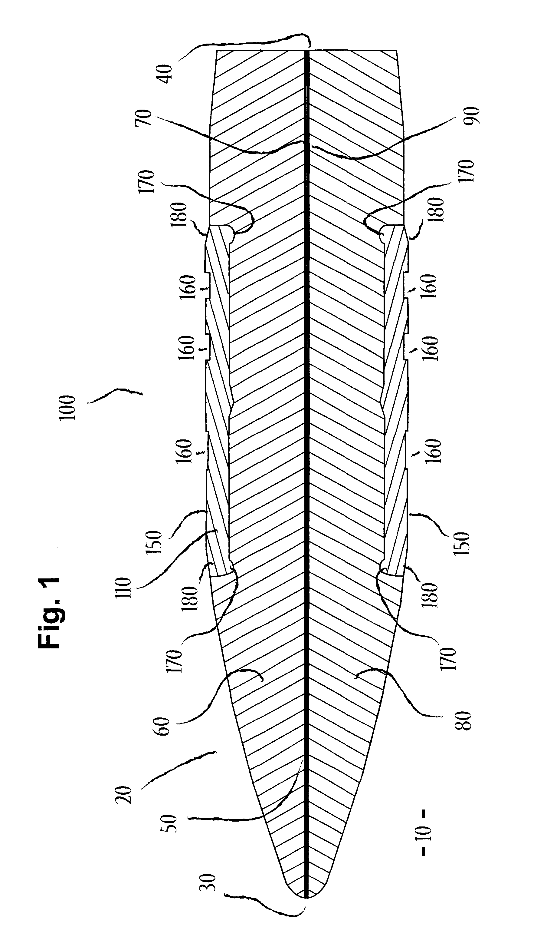
[0046]With reference now to the drawings, and in particular to FIG. 1 thereof, the new and improved longitudinally sectioned bullet embodying the principles and concepts of the present invention and generally designated by the reference numeral 10 will be described.
[0047]The present invention, the longitudinally sectioned bullet 10 is comprised of a plurality of components. Such components in their broadest context include a bullet body 20, with a front tip region 30 and a rear end or distal region 40 opposite the tip. A primary central longitudinal axis 50 spanning the length of the projectile, from the bullet tip 30 to its rear 40. A first longitudinal section 60 of the bullet body 20 has an internally facing surface 70. A second longitudinal section 80 of the bullet body 20 has an internally facing surface 90. In this embodiment, longitudinal sections 60 and 80 represent two halves of bullet body 20 divided longitudinally along primary central longitudinal axis 50 in which their ...
second embodiment
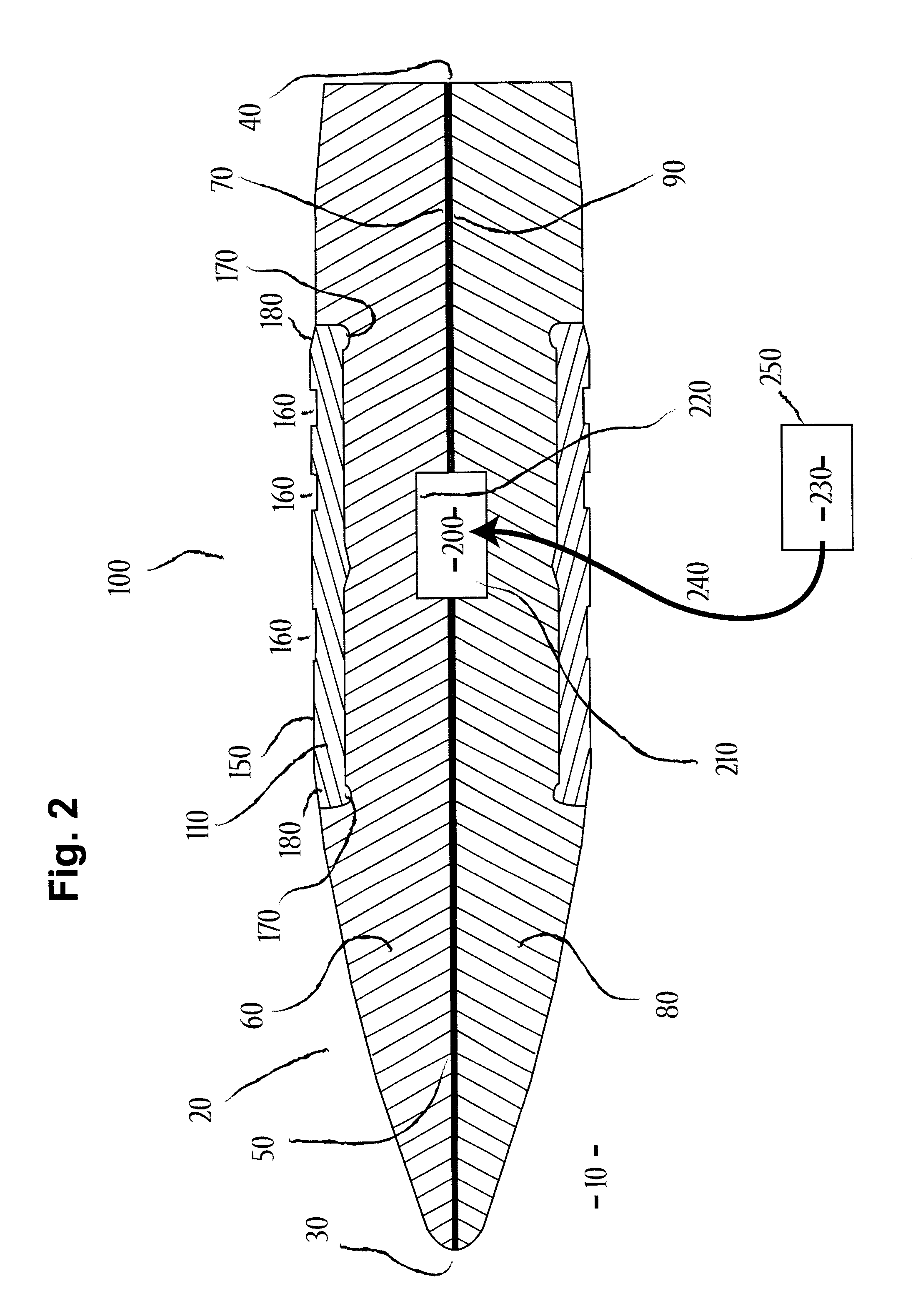
[0056]FIG. 2 shows the cross-section of a second bullet embodiment, similar to that of FIG. 1, but with an associated supplemental payload contained in a central cavity shared by both longitudinal sections. Another operative feature of at least some additional embodiments of the projectile 10, such as represented in FIG. 2, comprises the provision of a recess or cavity generally indicated as 200 within the bullet body 20. In this second embodiment, the recess or cavity 200 is formed between recesses 210 and 220 of longitudinal sections 60 and 80, along their internally facing surfaces 70 and 90. The combined recess or cavity 200 is structured and capable of containing and carrying at least one supplemental payload 230. Directional arrow 240 describes where supplemental payload 230 goes inside the bullet body cavity 200. The at least one supplemental payload is adapted to include, but is not limited to, at least one electronic circuit chosen from the class of tracking components incl...
fourth embodiment
[0060]FIG. 6 shows an exploded view of the cross-section of the fourth bullet embodiment shown in FIG. 5. Longitudinal sections 60 and 80 are labeled as 60 / 80 in this figure for convenience. Note that in this fourth embodiment, longitudinal sections 60 and 80 have been shortened at their rear end by a length similar to that of the dimension of reinforcement element 500, to accommodate and make room for said reinforcement element 500. Other reinforcements optionally appear at various other locations throughout the bullet body, and the current embodiment should not be construed as limiting.
[0061]FIG. 7 shows the cross-section of a fifth bullet embodiment, similar to that of FIGS. 3 and 4, but also includes at least one set, in this figure two sets, of at least partially interlocking prong-like elements 700 along internally facing surfaces 70 and 90 of longitudinal sections 60 and 80. These partially interlocking prong-like elements 700 provide additional structural support to the bull...
PUM
 Abstract
Description
Claims
Application Information
 - R&D
- Intellectual Property
- Life Sciences
- Materials
- Tech Scout
- Unparalleled Data Quality
- Higher Quality Content
- 60% Fewer Hallucinations
Browse by: Latest US Patents, China's latest patents, Technical Efficacy Thesaurus, Application Domain, Technology Topic, Popular Technical Reports.
© 2025 PatSnap. All rights reserved.Legal|Privacy policy|Modern Slavery Act Transparency Statement|Sitemap|About US| Contact US: help@patsnap.com


