System and method for performing ultrasonic pipeline wall property measurements

Active Publication Date: 2016-02-09
NEDERLANDSE ORG VOOR TOEGEPAST-NATUURWETENSCHAPPELIJK ONDERZOEK (TNO)
View PDF15 Cites 12 Cited by
  • Summary
  • Abstract
  • Description
  • Claims
  • Application Information

AI Technical Summary

Benefits of technology

[0017]In an embodiment the pipeline is supported by a support having a contact with the pipeline, the transmitters and receivers being coupled to the pipeline at mutually spaced circumferential positions along an line in the ax

Problems solved by technology

The initial first iterative model fitting process is applied to a sound frequency that is so low that it would not normally be used f

Method used


Image

  • System and method for performing ultrasonic pipeline wall property measurements
  • System and method for performing ultrasonic pipeline wall property measurements
  • System and method for performing ultrasonic pipeline wall property measurements

Examples


Embodiment Construction

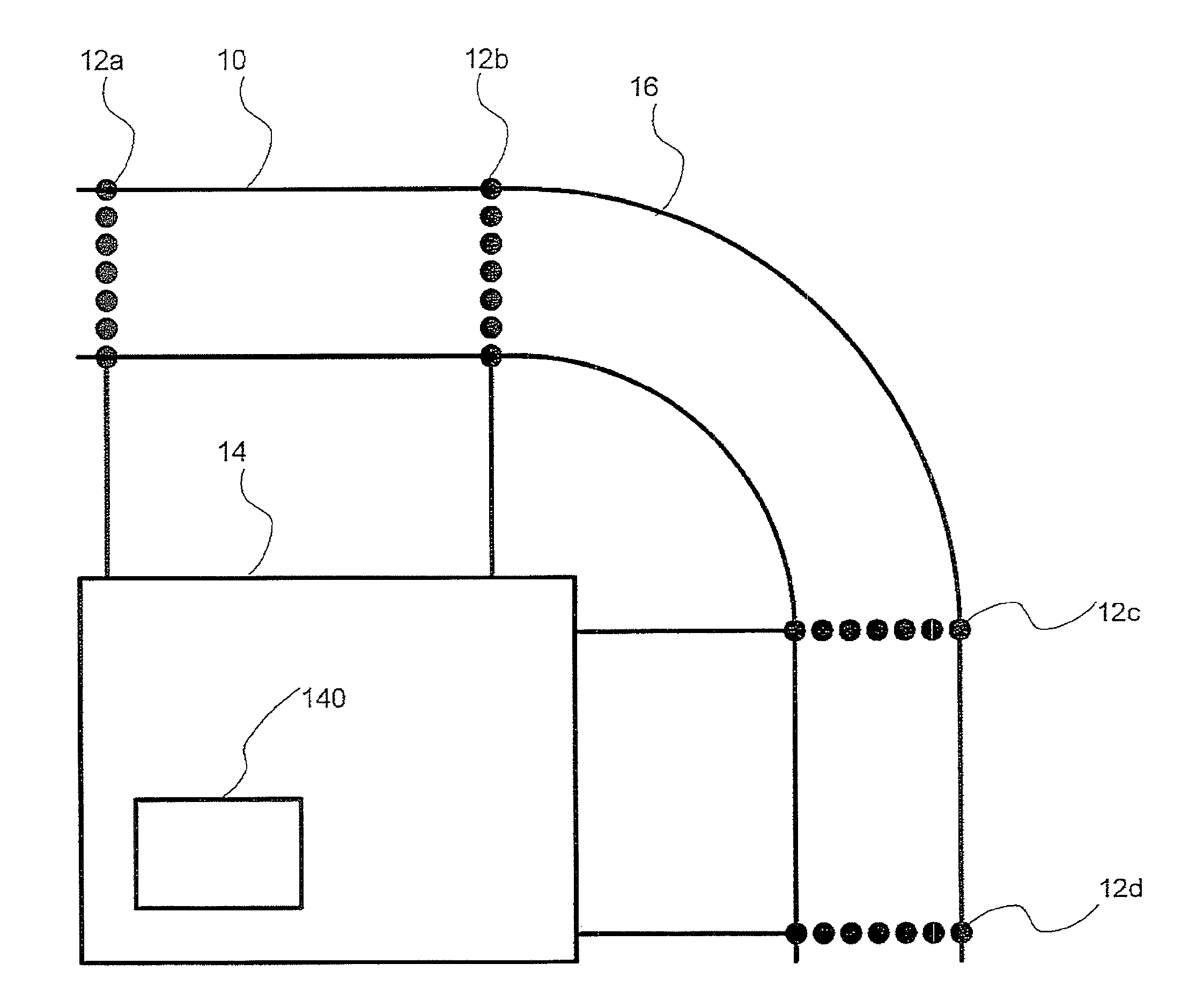
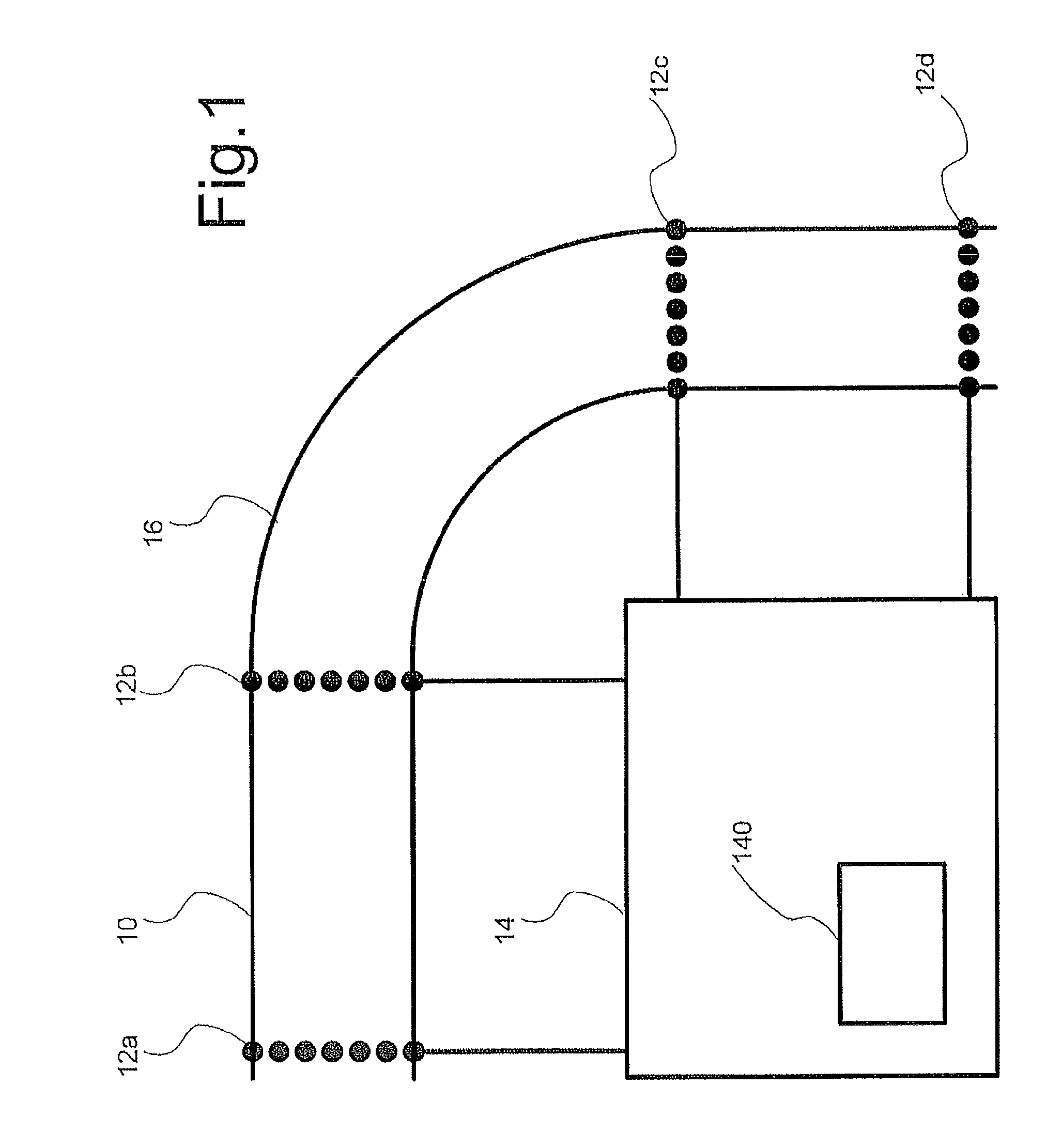
[0027]FIG. 1 shows a pipeline wall thickness measuring system comprising a pipeline 10 with rings of ultrasound transducers 12a-d coupled to pipeline 10 and an excitation and detection circuit 14 coupled to ultrasound transducers 12a-d. Excitation and detection circuit 14 comprises a signal processing circuit 140. Alternatively, a separate signal processing circuit, such as a computer programmed to perform signal processing may be coupled to excitation and detection circuit 14. Each ring extends circumferentially around pipeline 10 at a respective axial position. Each ring has a plurality of ultrasound transducers 12a-d at respective positions along the circumference at that axial position. As shown pipeline 10 has a bend 16, with rings of ultrasound transducers 12a-d on pipeline sections on both sides of the bend. In another embodiment one or more rings of ultrasound transducers 12a-d may be provided in bend 16.

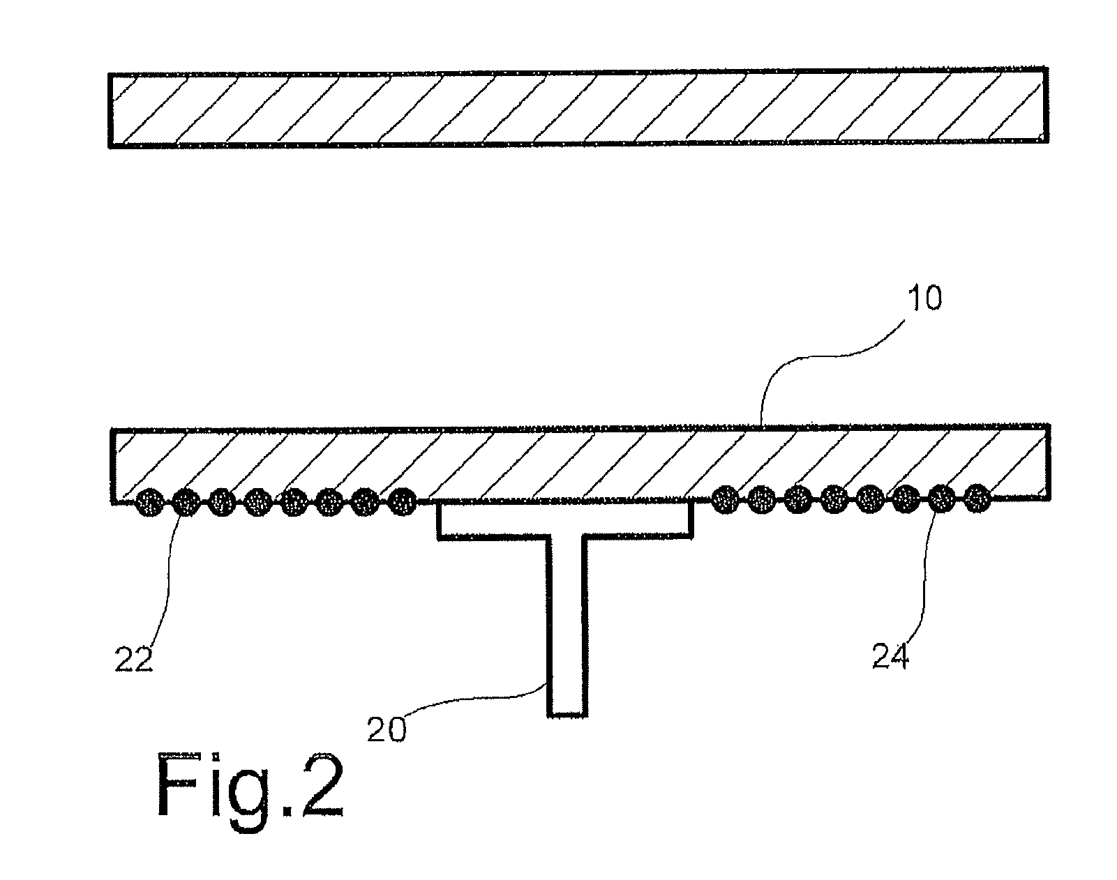
[0028]FIG. 2 shows an alternative pipeline wall thickness measuring sys...


PUM


Abstract

Pipeline wall thickness is measured as a function of position using ultrasound propagation. A series of predictive models is used, which define predictions of the ultrasound response signals as a function of different sets of parameters. The different sets that are determine of position dependent ultrasound speed at different sound frequencies and different spatial resolution. Successive iterative fitting process are executed, each fitting a combination of values of a successive set of parameters to the detected ultrasound response signals according to a respective model, using the values fitted values from the previous fitting process to initialize the next set of parameters for iterative fitting. At least the first model defines predictions of wave vector values as a function of circumferential position in successive rings around the pipe as sums of wave vector value for a plurality of circumferential positions in a preceding one of the rings multiplied by propagation coefficients, using propagation coefficients that depend on a first set of parameters.

Description

CROSS-REFERENCE TO RELATED APPLICATIONS[0001]This application is a 35 USC §371 U.S. national stage filing of International Patent Application No. PCT / NL2011 / 050686 filed on Oct. 7, 2011, which claims priority under the Paris Convention and 35 USC §119 to European Application No. 10186907.1, filed on Oct. 7, 2010.FIELD OF THE INVENTION DISCLOSURE[0002]The invention relates to a system and method for performing ultrasonic pipeline wall property measurements.BACKGROUND OF THE DISCLOSURE[0003]From WO 2008 / 10306 it is known to inspect pipelines for corrosion damage using ultrasonic signals. A transmitter is used to excite an ultrasound wave in the wall of a pipe and a detector is used to detect arrival of the ultrasound wave after it has travelled through the wall.[0004]The information that is obtained in this way can be used to form an image of damage in the pipe wall as a function of position along the wall surface. Properties of the wall are determined from the travel time, i.e. the d...

Claims


Application Information

Patent Timeline
IPC IPC(8): G01B17/02G01N29/07G01N29/04G01N29/44
CPCG01N29/07G01B17/02G01N29/04G01N29/4418G01N2291/105G01N2291/2634
Inventor VOLKER, ARNO WILLEM FREDERIKBLOOM, JOOST GERARDUS PETRUS
Owner NEDERLANDSE ORG VOOR TOEGEPAST-NATUURWETENSCHAPPELIJK ONDERZOEK (TNO)
Why Eureka
Try Eureka