Optical position detection device and display system with input function
a technology of optical position detection and display system, which is applied in the direction of measurement devices, instruments, beacon systems using ultrasonic/sonic/infrasonic waves, etc. it can solve the problems of narrow detection range, narrow detection range, and limited detection range, so as to accurately detect the position of the target object and grow in size
- Summary
- Abstract
- Description
- Claims
- Application Information
AI Technical Summary
Benefits of technology
Problems solved by technology
Method used
Image
Examples
first embodiment
Overall Configuration
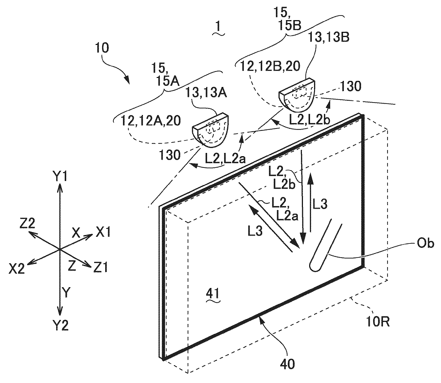
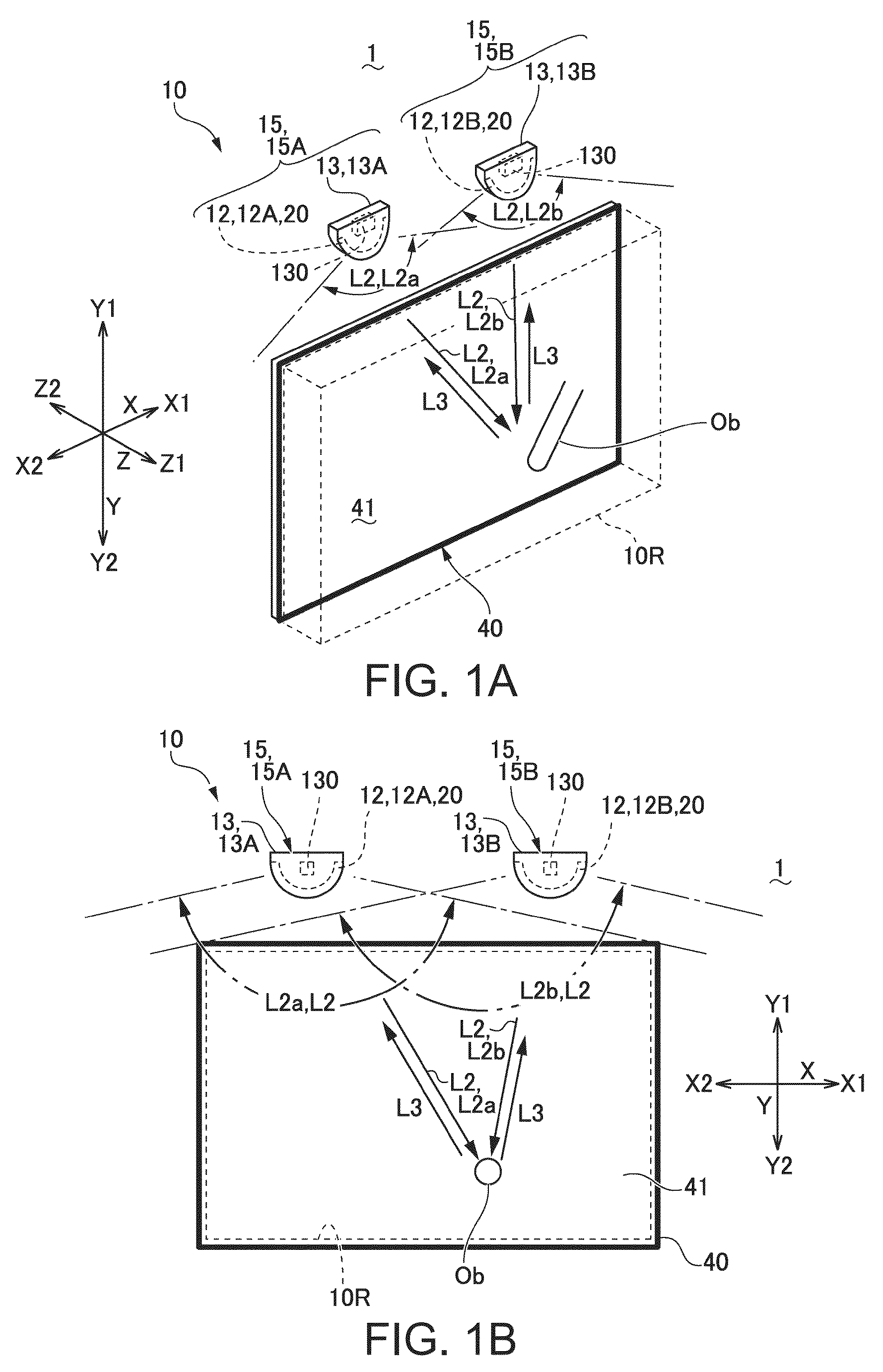
[0045]FIGS. 1A and 1B are explanatory diagrams of a substantial part of an optical position detection device according to a first embodiment of the invention. FIG. 1A is an explanatory diagram of the optical position detection device viewed in an oblique direction from the detection light emission space side, and FIG. 1B is an explanatory diagram of the optical position detection device viewed from the front thereof.
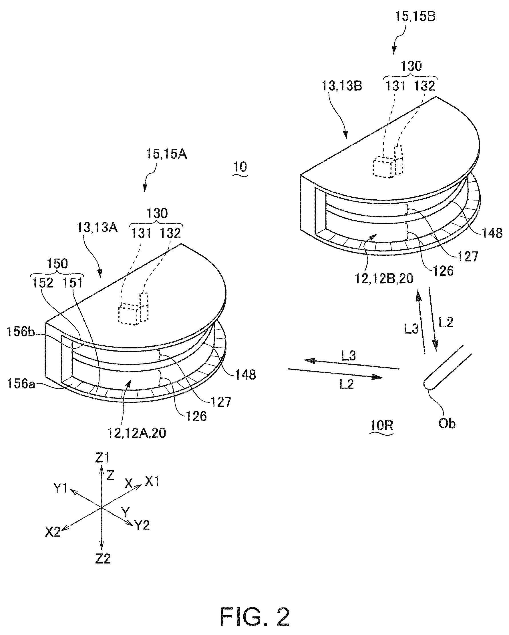
[0046]The position detection system 1 according to the present embodiment has an optical position detection device 10 for detecting the position of the target object Ob. The optical position detection device 10 detects the position of the target object Ob using detection light L2 emitted radially along an imaginary X-Y plane (an imaginary plane) defined by the X-axis direction and the Y-axis direction. In the present embodiment, the position detection system 1 has a visual plane forming member 40 having a visual plane 41 extending along the X-Y plane...
second embodiment
Configuration and Operation
[0096]FIGS. 11A through 11C are explanatory diagrams of the optical position detection device 10 according to the second embodiment of the invention, wherein FIG. 11A is an explanatory diagram showing a lighting operation and so on of the optical position detection device 10 according to the second embodiment of the invention, FIG. 11B is an explanatory diagram of the period during which the first light receiving element 131 is set to the detection mode, and FIG. 11C is an explanatory diagram of the period during which the second light receiving element 132 is set to the detection mode. FIGS. 12A and 12B are explanatory diagrams showing an electrical configuration of the amplification section 79 and so on of the optical position detection device 10 according to the second embodiment of the invention, wherein FIG. 12A is an explanatory diagram of a switching section of the electrical connection in the amplification section 79 and so on, and FIG. 12B is an e...
first specific example
of Position Detection System
[0115]FIG. 14 is an explanatory diagram of a first specific example (a display system with an input function) of a position detection system 1 to which the embodiment of the invention is applied. It should be noted that in the display system with the input function according to the present embodiment, since the configuration of the position detection system 1 and the optical position detection device 10 is substantially the same as the configuration explained with reference to FIGS. 1A, 1B, 2, 3, 4A, 4B, 5A, 5B, 6A, 6B, 7A, 7B, 8, 9A through 9D, 10, 11A through 11C, 12A, 12B, 13A, and 13B, the constituents common to the both configurations are denoted with the same reference symbols, and the explanation therefor will be omitted.
[0116]As shown in FIG. 14, in the position detection system 1 according to the present embodiment, by using the image display device 110 as the visual plane forming member 40, and disposing the optical position detection device 10 ...
PUM
 Abstract
Description
Claims
Application Information
 - R&D
- Intellectual Property
- Life Sciences
- Materials
- Tech Scout
- Unparalleled Data Quality
- Higher Quality Content
- 60% Fewer Hallucinations
Browse by: Latest US Patents, China's latest patents, Technical Efficacy Thesaurus, Application Domain, Technology Topic, Popular Technical Reports.
© 2025 PatSnap. All rights reserved.Legal|Privacy policy|Modern Slavery Act Transparency Statement|Sitemap|About US| Contact US: help@patsnap.com


