Procedure for the dynamic correction of the bending angle of sheet metal on a panel bender machine

a technology of bending angle and bending process, which is applied in the direction of metal-working equipment, metal-working safety devices, metal working apparatus, etc., can solve the problems of system confusion, laborious, slow and susceptible to manual procedure errors,

Active Publication Date: 2016-02-16
PRIMA IND
View PDF12 Cites 2 Cited by
  • Summary
  • Abstract
  • Description
  • Claims
  • Application Information

AI Technical Summary

Benefits of technology

[0040]This invention proposes to overcome the typical drawbacks and disadvantages of the prior art, and to provide a procedure for bending metal sheet on a panel bender machine which, avoiding the use of a display and manual actions, allows high precision bends to be made in a fully automatic manner.
[0044]In this way, any representation of the real and nominal bending lines on the display is avoided, as is the manual intervention of the operator, thereby shortening in a substantial manner the bending times of the metal sheet and improving the bending precision.

Problems solved by technology

In the hydraulic machines, the conventional kinematic chain of the pentalateral type is, however, used for providing twisting rigidity to the machine and, therefore, not with specific mechanical functions.
It may be noted that the system in the above-mentioned patent application does not execute any processing of the images, and does not obtain from them any additional information, and limits itself to showing them on the display and drawing on them a line corresponding to the desired bending angle.
For this reason, the system appears confused, laborious, slow and susceptible to errors in the manual procedure at the basis of its operation.

Method used


Image

  • Procedure for the dynamic correction of the bending angle of sheet metal on a panel bender machine
  • Procedure for the dynamic correction of the bending angle of sheet metal on a panel bender machine

Examples


Embodiment Construction

[0040]This invention proposes to overcome the typical drawbacks and disadvantages of the prior art, and to provide a procedure for bending metal sheet on a panel bender machine which, avoiding the use of a display and manual actions, allows high precision bends to be made in a fully automatic manner.

[0041]This is achieved by means of a procedure having the characteristics described in claim 1.

[0042]The dependent claims describe particularly advantageous embodiments of the procedure according to this invention.

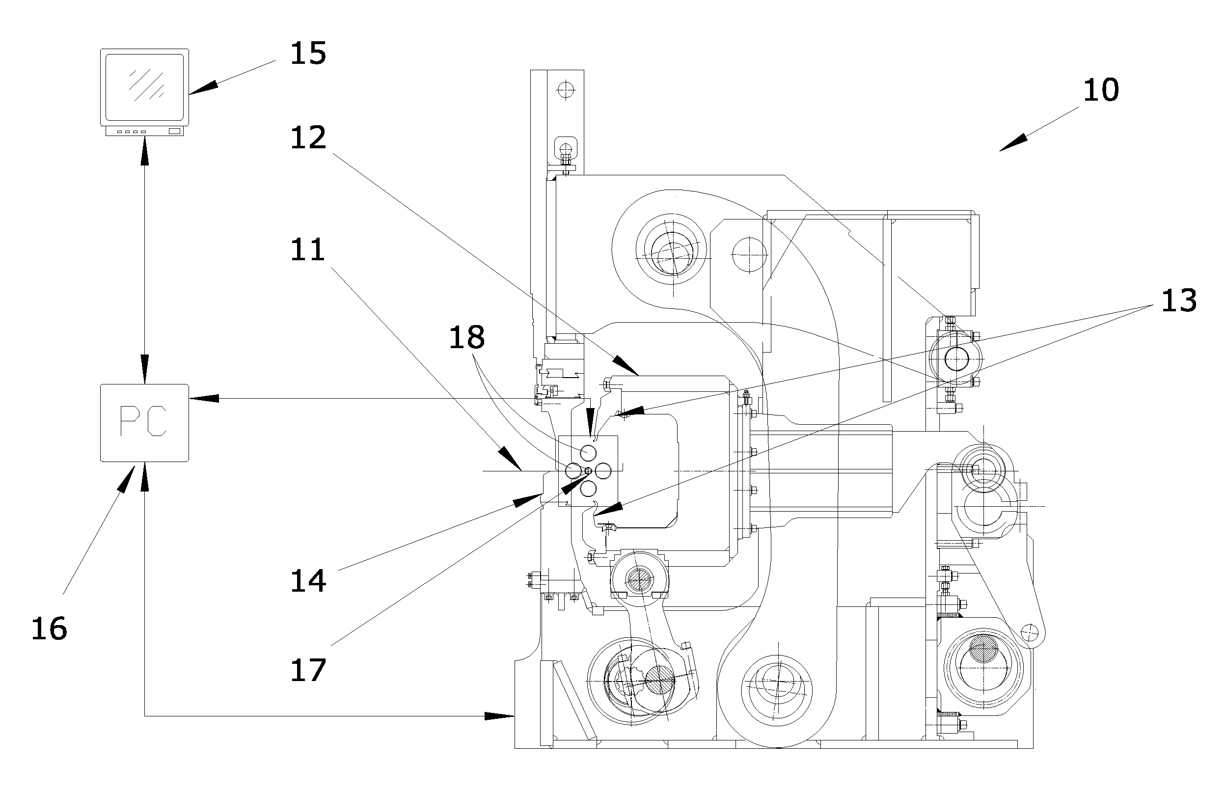
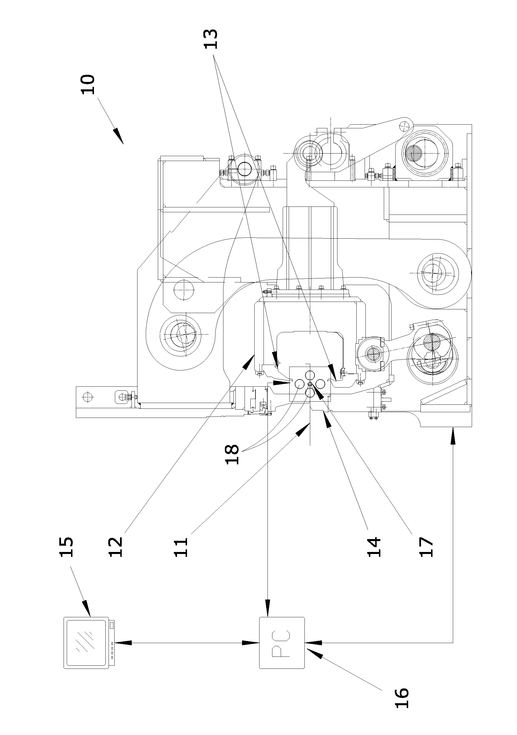
[0043]The procedure according to this invention is implemented using a TV camera which is able to acquire a digital image of the bend made, and suitable software for digital processing of the image which is able calculate, in a fully automatic manner and without requiring the graphical representation of the bend on a display, the deviation relative to a nominal bending angle and to give a command to the machine control PLC for repositioning the bending blades of the panel bende...


PUM

PropertyMeasurementUnit
bendingaaaaaaaaaa
thicknessaaaaaaaaaa
angleaaaaaaaaaa

Abstract

Described is a procedure for bending a sheet of sheet metal on a panel bender machine wherein upon bending the sheet of metal sheet a first software (BE) for machine control transmits to a second software (VS) for management of a TV camera (17), positioned in alignment with the bending line, the data relating to the nominal bending angle, the bending length, the distance of the bent edge from the center line of the panel bender and the thickness of the metal sheet. The second software (VS) acquires an image of the bent metal sheet, identifies the spatial position of the straight line corresponding to the bent edge of the sheet of sheet metal and then calculates its geometric coordinates in accordance with a preset referencing system, and supplies to the first software (BE) the value of the angle of the bend performed. The machine control is returned to the first software (BE), which calculates the difference between the angle of the bend actually performed and the angle of the nominal bend and then orders the start of a new bend corresponding to the angular difference, thereby obtaining a bend corresponding to the nominal bend.

Description

TECHNICAL FIELD[0001]This invention relates to a procedure for bending sheet metal on a panel bender machine.[0002]More specifically, this invention relates to a procedure by which it is possible to bend metal sheets in an extremely precise manner, using a unit which is able to perform, in a fully automatic manner, digital processing of the bends and to correct, again automatically, the bends the angles of which differ from the preset nominal bending angles.[0003]The invention is mainly applied in the field of panel bender machines for making metal sheet profiles.BACKGROUND ART[0004]It is known that panel bender machines are used in the industry for the manufacture of metal sheet products which allow a succession of bends to be made on the same metal sheet, in such a way as to obtain a finished product such as, for example, the hood of a cooker or the shelf of a stand.[0005]It is also known that the panel bender machines or metal sheet benders normally consist of:[0006]a fixed workb...

Claims


Application Information

Patent Timeline
Patent Type & Authority Patents(United States)
IPC IPC(8): B21D5/04B21D5/00
CPCB21D5/004B21D5/006B21D5/045
Inventor FRIGO, ANDREA
Owner PRIMA IND
Why Eureka
Try Eureka