Dual stage piloted force reduction valve

a piloted force and valve technology, applied in the direction of servomotors, servomotor components, servometer circuits, etc., can solve the problems of reducing the operating length of the hydraulic cylinder. , to achieve the effect of increasing reducing the operating length of the hydraulic cylinder

Active Publication Date: 2016-02-16
DEERE & CO
View PDF5 Cites 0 Cited by
  • Summary
  • Abstract
  • Description
  • Claims
  • Application Information

AI Technical Summary

Benefits of technology

[0017]It is a third aspect of the present invention to provide a method of operating a pressurized fluid subassembly comprising: (a) actively supplying a fluid at a high pressure to a fluid driven actuator and to a sequence valve, where the fluid at the high pressure supplied to the fluid driven actuator is operative to actively reposition the fluid driven actuator, the fluid at the high pressure supplied to the sequence valve increases a bias of the sequence valve to inhibit fluid communication between the fluid at the high pressure and a lower pressure drain; and, (b) discontinuing actively supplying the fluid at the high pressure to the fluid driven actuator and to the sequence valve, where discontinuing actively supplying the fluid at the high pressure to the fluid driven actuator discontinues active repositioning of the fluid driven actuator, and where discontinuing actively supplying the fluid at the high pressure to the sequence valve reduces the bias of the sequence valve to allow fluid communication between the lower pressure drain and the fluid driven actuator when a pressure of the fluid within the fluid driven actuator exceeds a maximum working pressure.
[0019]It is a fourth aspect of the present invention to provide a method of operating a pressurized fluid subassembly comprising utilizing a sequence valve in fluid communication with a head side chamber of a hydraulic cylinder to reduce a head side fluid pressure within the head side chamber when the head side fluid pressure exceeds a rod side fluid pressure within a rod side chamber of the hydraulic cylinder by more than a predetermined pressure differential.
[0020]In a more detailed embodiment of the fourth aspect, the method further comprises repositioning the hydraulic cylinder by operating a control valve to concurrently establish fluid communication between a high pressure fluid source and the head side chamber and the rod side chamber of the hydraulic cylinder to increase an operating length of the hydraulic cylinder, and the sequence valve to bias the sequence valve to a first sequence discontinuing fluid communication between the high pressure fluid source and a low pressure drain. In yet another more detailed embodiment, the method further comprises discontinuing repositioning the hydraulic cylinder by operating the control valve to concurrently discontinue fluid communication between the high pressure fluid source and (a) the head side chamber and the rod side chamber of the hydraulic cylinder to maintain the operating length of the hydraulic cylinder, and (b) the sequence valve to reduce a bias of the sequence valve to allow fluid communication between the head side chamber and the low pressure drain when the head side fluid pressure exceeds the rod side fluid pressure within the rod side chamber of the hydraulic cylinder by more than the predetermined pressure differential.
[0021]In a further detailed embodiment, the method further comprises repositioning the hydraulic cylinder by operating the control valve to concurrently establish fluid communication between the high pressure fluid source and (a) the rod side chamber of the hydraulic cylinder to decrease the operating length of the hydraulic cylinder, and (b) the sequence valve to bias the sequence valve to the first sequence discontinuing fluid communication between the high pressure fluid source and the low pressure drain. In still a further detailed embodiment, the method further comprises discontinuing repositioning the hydraulic cylinder by operating a control valve to concurrently discontinue fluid communication between a high pressure fluid source and (a) the head side chamber and the rod side chamber of the hydraulic cylinder to maintain an operating length of the hydraulic cylinder, and (b) the sequence valve to reduce a bias of the sequence valve to allow a second sequence establishing fluid communication between the head side chamber and a low pressure drain when the head side fluid pressure exceeds the rod side fluid pressure within the rod side chamber of the hydraulic cylinder by more than the predetermined pressure differential.

Problems solved by technology

While laying down the cut tree, the feller head and boom may be subjected to kick-back or rebound forces as the tree bounces on the ground.
More specifically, the rebound forces applied to the hydraulic cylinders result in rapid hydraulic pressure increases within the cylinders, sometimes resulting in cylinder failure.
While one alternative would be incorporation of larger, more robust hydraulic cylinders, this incorporation has ripple effects that require many other components such as the hydraulic pump and hoses to be more robust and substantially less efficient.
Additional issues are also encountered such as, without limitation, additional weight and potential redesign of the feller head and feller boom to withstand the increased forces that can be transmitted by more robust hydraulic cylinders.

Method used


Image

  • Dual stage piloted force reduction valve
  • Dual stage piloted force reduction valve
  • Dual stage piloted force reduction valve

Examples


Embodiment Construction

[0028]The exemplary embodiments of the present disclosure are described and illustrated below to encompass methods and devices for use with fluid control systems, such as hydraulic control systems. Of course, it will be apparent to those of ordinary skill in the art that the embodiments discussed below are exemplary in nature and may be reconfigured without departing from the scope and spirit of the present invention. However, for clarity and precision, the exemplary embodiments as discussed below may include optional steps, methods, and features that one of ordinary skill should recognize as not being a requisite to fall within the scope of the present invention.

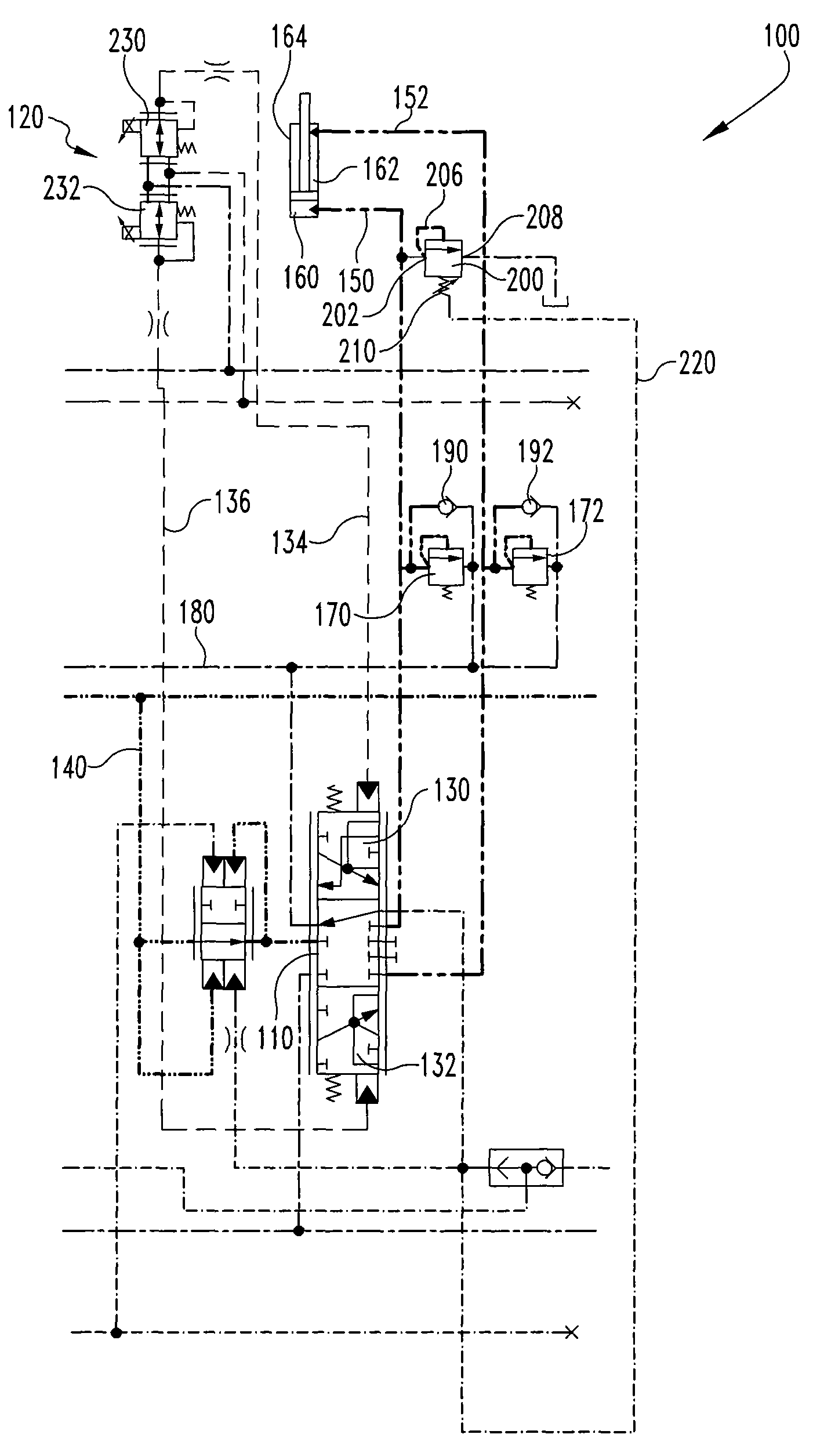
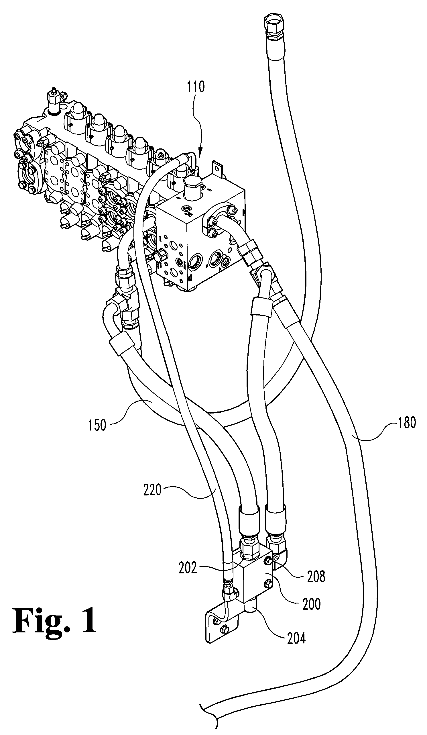
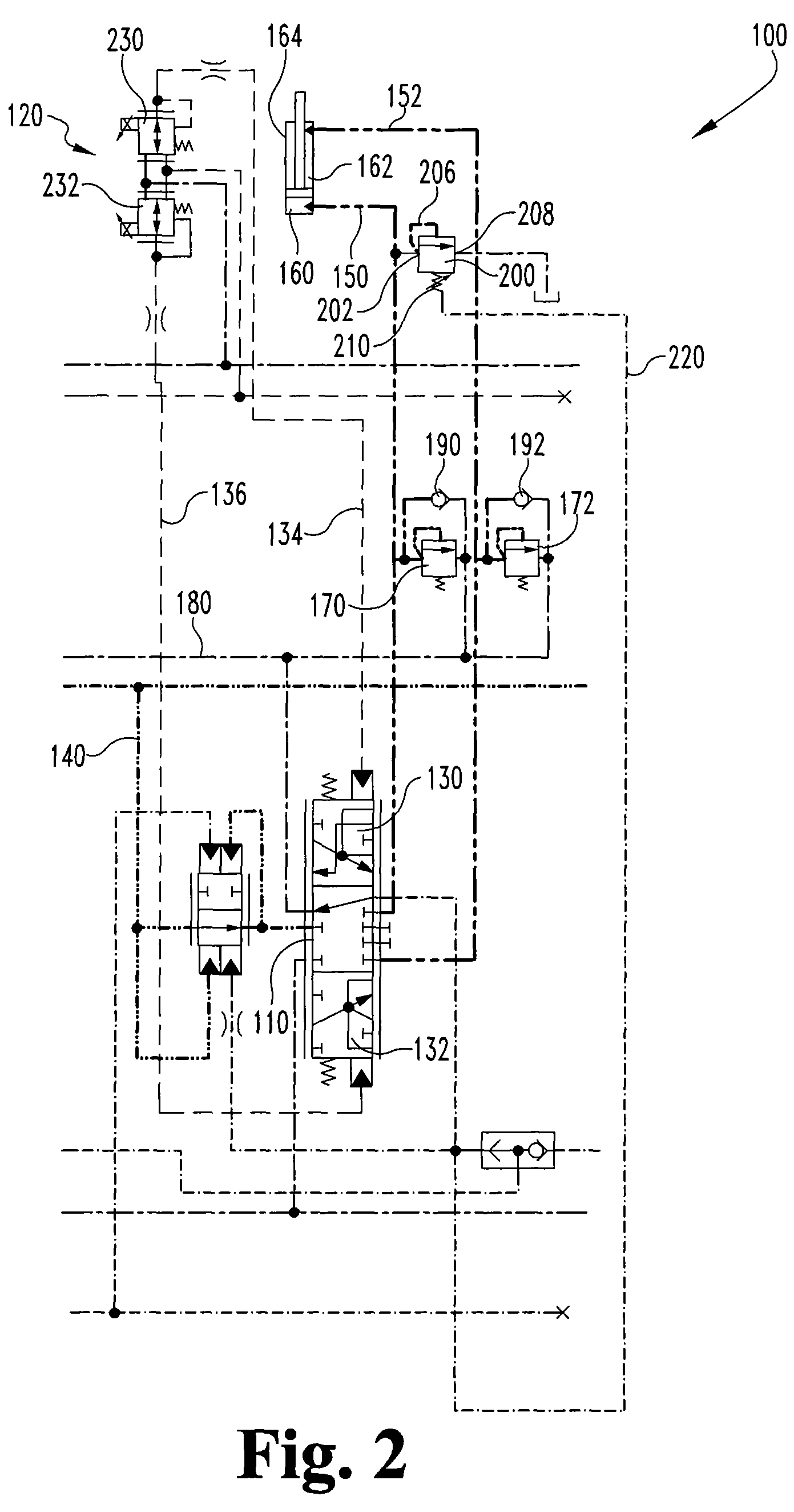
[0029]Referring to FIGS. 1-4, an exemplary hydraulic sub-system 100 is a component of a larger hydraulic system for an industrial piece of equipment. By way of example, the exemplary hydraulic sub-system 100 may be incorporated as part of an overall hydraulic control system such as for a 900K-Series feller buncher manufactu...


PUM


Abstract

A pressurized fluid subassembly comprising: (a) a fluid driven actuator configured to utilize fluid at a high pressure to change an overall length of the fluid driven actuator; and, (b) a sequence valve interposing a low pressure line and a supply line conveying the fluid to the fluid driven actuator, the sequence valve including a first sequence configured to inhibit fluid communication between the supply line and the low pressure line when the fluid at the high pressure is actively supplied to the fluid driven actuator, the sequence valve including a second sequence configured to establish fluid communication between the supply line and the low pressure line when the fluid at the high pressure is not actively supplied to the fluid driven actuator, wherein the sequence valve includes a variable bias that changes depending upon whether the fluid at the high pressure is actively supplied to the fluid driven actuator.

Description

FIELD OF THE INVENTION[0001]The present invention is directed to methods and devices utilized as part of a pressurized fluid delivery system.BACKGROUND OF THE INVENTION[0002]Those familiar with timber harvesting are familiar with feller bunchers, such as the 900K-Series feller buncher manufactured and sold by John Deere. Feller bunchers are utilized to rapidly harvest trees using a boom to reposition a felling head. Typical felling heads have a large disc saw that is used to cut the base of a tree, while repositionable arms of the felling head are used to grasp the stem of the tree as the tree is being cut. While the tree is being cut and after the tree is severed from its base, it continues to be grasped by the felling head arms and rides upon a butt plate. The operator of the feller buncher then tilts the felling head and allows gravity to lay the tree down.[0003]While laying down the cut tree, the feller head and boom may be subjected to kick-back or rebound forces as the tree bo...

Claims


Application Information

Patent Timeline
Patent Type & Authority Patents(United States)
IPC IPC(8): F15B13/04F15B11/028
CPCF15B11/028F15B2211/30535F15B2211/3122F15B2211/50518F15B2211/5159F15B2211/528F15B2211/55F15B2211/5753
Inventor RAMLER, MATTHEW J.RASZGA, CALIN
Owner DEERE & CO
Why Eureka
Try Eureka