Automatic transmission controller

a transmission controller and automatic technology, applied in the direction of brake systems, transportation and packaging, gearing, etc., can solve the problems of difficult detection of backward movement by ordinary sensors, inability to prevent vehicle backward movement on the slope,

Active Publication Date: 2016-02-16
HONDA MOTOR CO LTD
View PDF14 Cites 0 Cited by
  • Summary
  • Abstract
  • Description
  • Claims
  • Application Information

AI Technical Summary

Benefits of technology

[0005]To improve driving performance and drivability, the number of gear ratios of an automatic transmission for an automobile is being increased. In general, an automatic transmission includes engagement mechanisms, such as planetary gear mechanisms, clutches, and brakes. The gear ratio of the automatic transmission is changed by changing the power transmission path by using the engagement mechanisms. Such an automatic transmission includes a torque converter (starting mechanism) that is disposed between a drive source and a driving wheel of a vehicle and that transmits rotational power from the drive source to the driving wheel.
[0093]Control of transition from idling N control to forward first gear can be performed by changing only one engagement. Therefore, control can be easily performed.
[0094]With the embodiment of the present disclosure, a sensor for detecting a backward movement and a sensor for detecting the brake pressure, which are used in existing technologies, are not necessary. Therefore, backward movement of the vehicle can be restricted without providing the vehicle with special devices. As a result, the cost, the weight, and the fuel efficiency can be improved.

Problems solved by technology

When a vehicle that performs idling N control stops on, for example, an uphill slope, it is not possible to prevent backward movement of the vehicle on the slope because the torque converter does not have a creep torque or has only a very small creep torque.
The rotation sensor, which actively detects backward movement, has a special structure because it is difficult for an ordinary sensor to detect backward movement of a vehicle because the rotational speed of a wheel of the vehicle is low when the vehicle moves backward.

Method used


Image

  • Automatic transmission controller
  • Automatic transmission controller
  • Automatic transmission controller

Examples


Embodiment Construction

[0030]The embodiments will now be described with reference to the accompanying drawings, wherein like reference numerals designate corresponding or identical elements throughout the various drawings.

Structure of Engagement Mechanism of Automatic Transmission

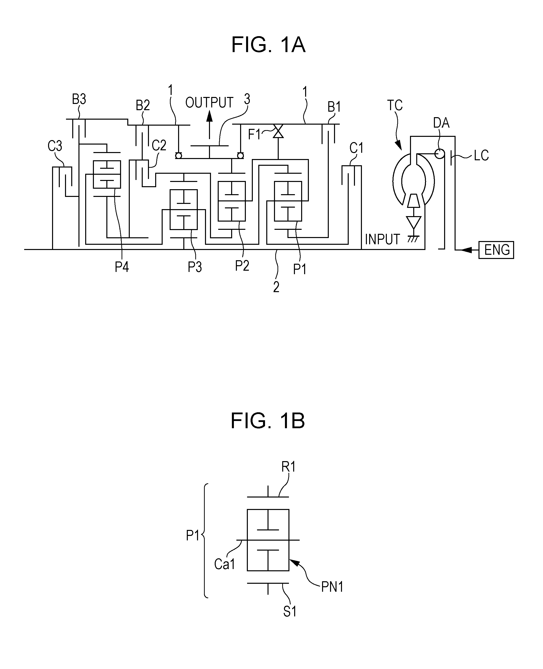
[0031]FIG. 1A illustrates an automatic transmission according to an embodiment of the present disclosure, which has ten forward gears and one reverse gear. The automatic transmission includes a casing 1, an input shaft 2, and an output member 3. The input shaft 2 is rotatably supported in the casing 1. A driving force that is output from a drive source ENG, such as an internal combustion engine or the like, is transmitted to the input shaft 2 through a torque converter TC that includes a lock-up clutch LC and a damper DA. The output member 3 includes an output gear that is disposed coaxially with the input shaft 2. Rotation of the output member 3 is transmitted to left and right driving wheels of a vehicle through a differential ...


PUM


Abstract

An automatic transmission controller for controlling an automatic transmission includes a neutral controller which is configured to perform neutral control, a neutral control permission determiner, and an engagement controller. The automatic transmission includes a plurality of planetary gear mechanisms and a plurality of engagement mechanisms. One of the plurality of engagement mechanisms is a mechanical engagement mechanism. The engagement controller is configured to allow rotation of an input shaft of the automatic transmission in a case where the neutral control determiner permits the neutral control and configured to set the plurality of engagement mechanisms including at least the mechanical engagement mechanism so as to fix an output shaft of the automatic transmission to a casing of the automatic transmission in a case where the output shaft of the automatic transmission is rotated by a wheel of a vehicle in a rotational direction such that the vehicle moves backward.

Description

CROSS-REFERENCE TO RELATED APPLICATIONS[0001]The present application claims priority under 35 U.S.C. §119 to Japanese Patent Application No. 2013-123165, filed Jun. 11, 2013, entitled “Automatic Transmission Controller.” The contents of this application are incorporated herein by reference in their entirety.BACKGROUND[0002]1. Field[0003]The present disclosure relates to an automatic transmission controller.[0004]2. Description of the Related Art[0005]To improve driving performance and drivability, the number of gear ratios of an automatic transmission for an automobile is being increased. In general, an automatic transmission includes engagement mechanisms, such as planetary gear mechanisms, clutches, and brakes. The gear ratio of the automatic transmission is changed by changing the power transmission path by using the engagement mechanisms. Such an automatic transmission includes a torque converter (starting mechanism) that is disposed between a drive source and a driving wheel of...

Claims


Application Information

Patent Timeline
Patent Type & Authority Patents(United States)
IPC IPC(8): F16H3/66F16H61/00
CPCF16H3/66F16H3/666F16H61/0059F16H2200/0069F16H2200/2012F16H2200/2046F16H2200/2082F16H2312/04F16H61/0204F16H61/20F16H2061/0234F16H2061/207B60T7/122F16H2061/6608
Inventor TACHIBANADA, YUYAISHIKAWA, YUTAKA
Owner HONDA MOTOR CO LTD
Why Eureka
Try Eureka