
Device for tempering a receptacle in a chamber

a technology for tempering devices and receptacles, which is applied in the direction of positioning apparatuses, metal-working machine components, manufacturing tools, etc., can solve the problems of sealing being impaired in the tempering devi

Inactive Publication Date: 2016-02-23
DOCKWEILER
View PDF16 Cites 0 Cited by
  • Summary
  • Abstract
  • Description
  • Claims
  • Application Information

AI Technical Summary

Benefits of technology

[0008]An object of the invention is to provide a device for tempering a receptacle in a chamber, which allows with simple means an appropriate and effective sealing of the chambers inside the device.
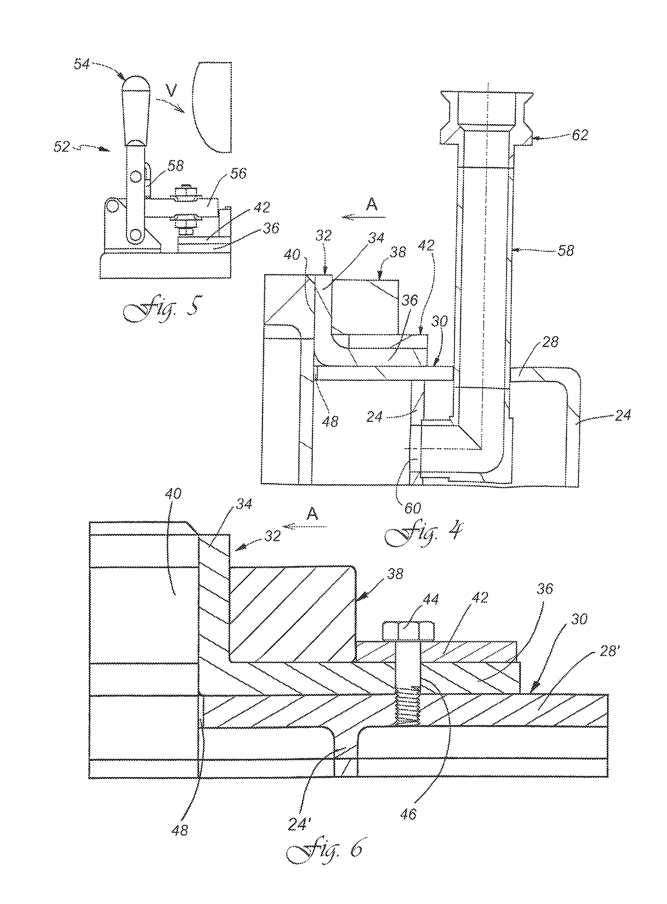
[0009]The device according to the invention is provided and determined to temper a receptacle, in particular a bubbler, in a chamber. The device has a cylindrical casing, which surrounds the chamber. Furthermore, a bottom is provided, which is arranged on an end of the casing and is connected with it. Furthermore, an opening with a contact surface running parallel to the bottom, which limits the diameter of the opening with respect to the inner diameter of the chamber, is located on the end opposite the bottom. The receptacle to be tempered is placed in the chamber through the opening. According to the invention, an annular sealing element, which has a sealing leg and a contact leg, wherein the contact leg lies on the contact surface, is provided. Additionally, an annular tensioning element is provided, which is placed on the sealing element and lies on the sealing leg on its outside. By setting the tensioning element, the sealing leg with its inside can be tensioned against the outside of the receptacle and the chamber can thus be sealed off. The advantage of an annular sealing element that has two legs is that the seal can be removed from the chamber for inserting and removing the receptacle and thus the receptacle is particularly easy to arrange in and remove from the chamber. Moreover, different outer diameters of the receptacle can be compensated for by the tensioning element. The entire device can also be used for receptacles with different diameters by selecting a suitable sealing element and the suitable tensioning element. Through the seal according to the invention via a tensioned sealing element, it is also made possible to operate the tempering device with excess pressure, i.e. to incorporate a pressurized tempering medium in the intermediate space between the receptacle and the inside of the chamber wall.
[0014]In a preferred embodiment, an inflow tube for the tempering medium flows into the base of the chamber, preferably centrally on the base below a receptacle arranged in the chamber. Through the tempering medium introduced below the receptacle, it can be distributed well in the chamber and the receptacle can be tempered evenly.

Problems solved by technology

Since bubblers have tolerances and irregularities in their circumferential diameter caused for example by welded seams, the seal can be impaired in the tempering device.

Method used


Image

  • Device for tempering a receptacle in a chamber
  • Device for tempering a receptacle in a chamber
  • Device for tempering a receptacle in a chamber

Examples


Embodiment Construction

[0028]While this invention may be embodied in many different forms, there are described in detail herein a specific preferred embodiment of the invention. This description is an exemplification of the principles of the invention and is not intended to limit the invention to the particular embodiment illustrated.

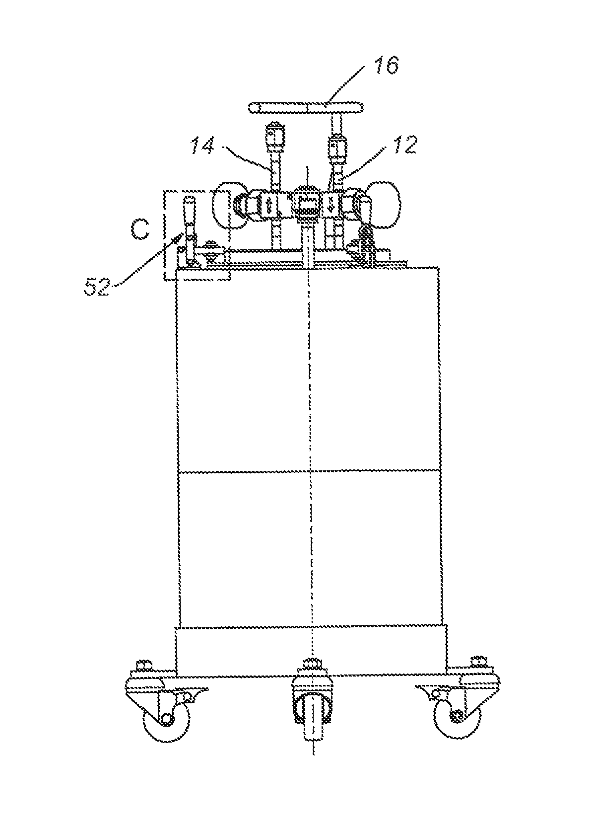
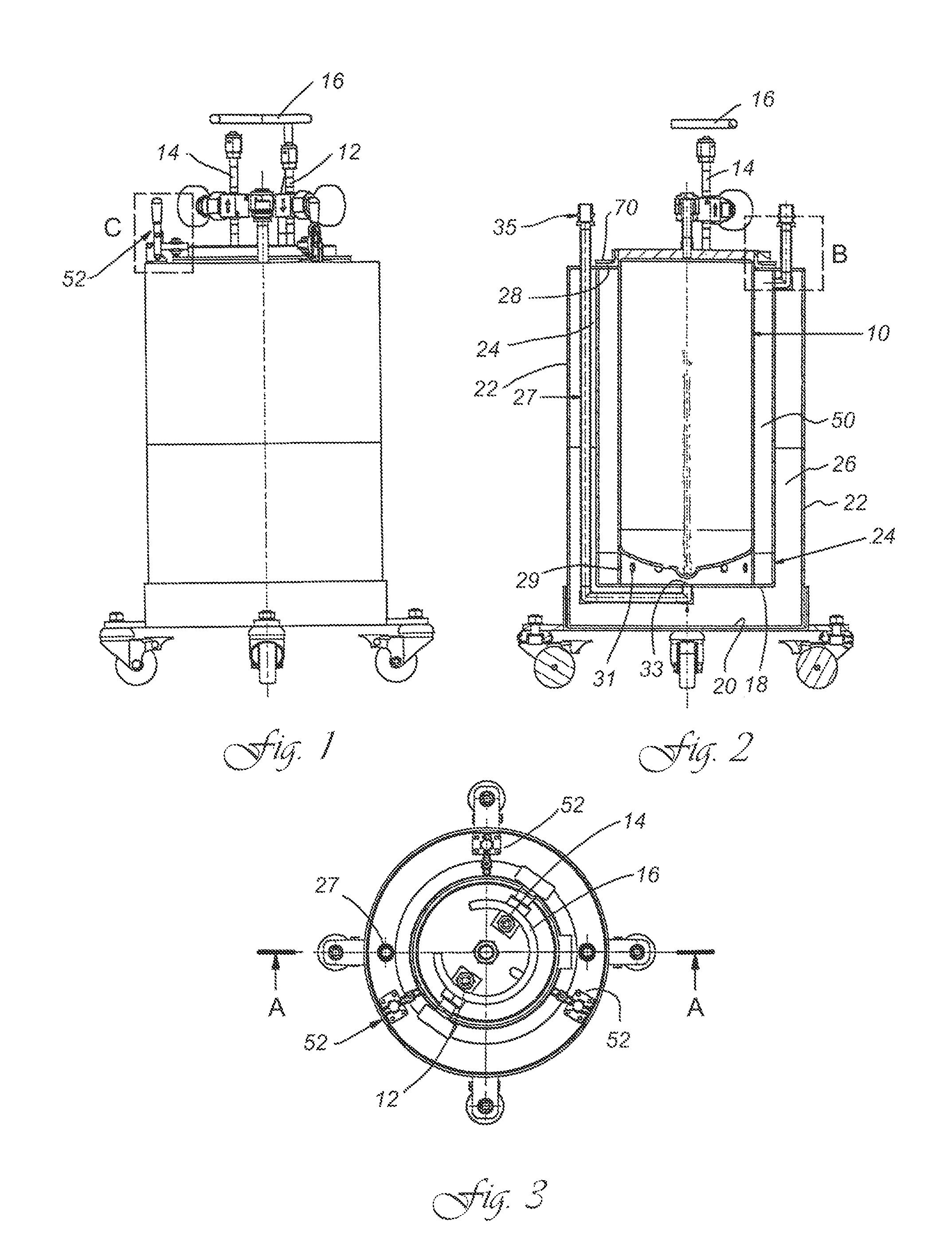
[0029]FIG. 2 shows a cylindrical bubbler 10 with its supply and drain lines 12 and 14 in cross-section. H2 gas is for example supplied to the bubbler via the supply line 12, where it reacts chemically and escapes again as doping gas via the drain line 14. For handling purposes, the bubbler has a centrally arranged handle 16, which is designed as a ring segment. In FIG. 1, the bubbler is inserted into the tempering device so that the connections for the supply and drain lines and the handle protrude from the tempering device.

[0030]The tempering device is designed double-walled in the example shown, wherein an inner bottom wall 18 and an outer bottom wall 20 are provided. The o...


PUM


Abstract

A device for tempering a receptacle in a chamber, including a cylindrical casing surrounding the chamber, a bottom, which is arranged on an end of the casing and is connected with it, an opening on an end of the casing opposite to the bottom, which is limited by a contact surface running parallel to the bottom, an annular sealing element, which has a sealing leg and a contact leg, which rests on the contact surface and an annular tensioning element, which, placed on the sealing element, lies on the sealing leg on its outside.

Description

CROSS-REFERENCE TO RELATED APPLICATIONS[0001]Not applicable.STATEMENT REGARDING FEDERALLY SPONSORED RESEARCH[0002]Not applicable.BACKGROUND OF THE INVENTION[0003]The present invention relates to a device for tempering a receptacle in a chamber.[0004]There is the need to precisely temper receptacles in which chemical media react with each other. Thus, it is for example known for chemical vapor deposition processes and / or for the doping of semi-conductors to very precisely temper a receptacle, also known as a bubbler, in which a doping gas is created, in a tempering device. For this, the receptacle is arranged in the tempering device and sealed outwardly. Since bubblers have tolerances and irregularities in their circumferential diameter caused for example by welded seams, the seal can be impaired in the tempering device. The tempering device is well insulated and is tempered in its chamber via a medium such as water or another tempering medium.[0005]A cover closure for a pressure con...

Claims


Application Information

Patent Timeline
Patent Type & Authority Patents(United States)
IPC IPC(8): B23Q3/00B23Q3/18H01L21/67
CPCH01L21/67017B23Q3/18Y02E60/321Y02E60/32
Inventor FIEBIG, KLAUS-DIETER
Owner DOCKWEILER
Learn More