Supercharge Your Innovation With Domain-Expert AI Agents!

Phase shift circuit and power factor correction circuit including the same

a technology of phase shift circuit and power factor, applied in the direction of electric variable regulation, process and machine control, instruments, etc., can solve the problems of large form factor type low effect of power factor correction circuit, so as to raise lower the level of control signal

Active Publication Date: 2016-02-23
SKAICHIPS CO LTD
View PDF13 Cites 1 Cited by
  • Summary
  • Abstract
  • Description
  • Claims
  • Application Information

AI Technical Summary

Benefits of technology

[0019]According to another aspect of the present invention, there is provided a power factor correction circuit including: a detection circuit unit detecting currents from inductors respectively included in a main circuit and a sub-circuit to generate a voltage pulse signal; a controlling unit generating a control signal based on the voltage pulse signal; and a driving circuit unit determining operations of switches respectively included in the main circuit and the sub-circuit, based on the control signal and the voltage pulse signal, wherein the controlling unit generates the control signal to allow driving signals for respectively operating the switch included in the main circuit and the switch included in the sub-circuit to have a phase difference therebetween so as to allow electromagnetic interference (EMI) to be significantly decreased.
[0022]The control signal generating circuit may raise the level of the control signal when a phase of the voltage pulse signal generated from the current of the inductor included in the sub-circuit leads a phase of the reference clock signal, and may lower the level of the control signal when the phase of the voltage pulse signal generated from the current of the inductor included in the sub-circuit lags behind the phase of the reference clock signal.

Problems solved by technology

The passive-type power factor correction circuit has disadvantages in that a form factor thereof may be large, and an effect thereof may not be great.
However, in the phase shift circuit suggested in the related art, a selection condition in selecting a current source included in the circuit was limited or it was difficult to accurately generate a required phase difference.

Method used


Image

  • Phase shift circuit and power factor correction circuit including the same
  • Phase shift circuit and power factor correction circuit including the same
  • Phase shift circuit and power factor correction circuit including the same

Examples


Embodiment Construction

[0034]Hereinafter, embodiments of the present invention will be described in detail with reference to the accompanying drawings. The invention may, however, be embodied in many different forms and should not be construed as being limited to the embodiments set forth herein.

[0035]Rather, these embodiments are provided so that this disclosure will be thorough and complete, and will fully convey the scope of the invention to those skilled in the art.

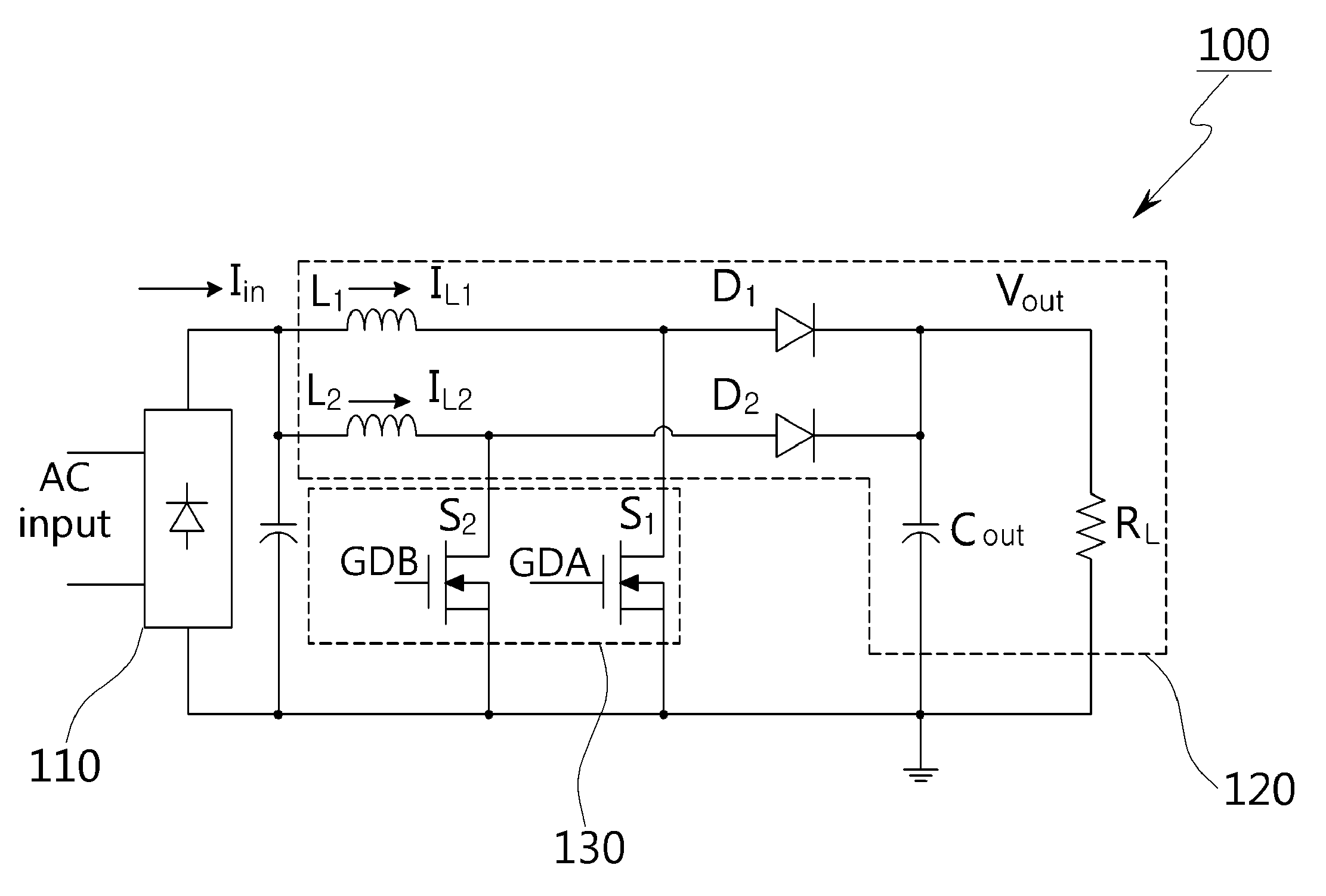
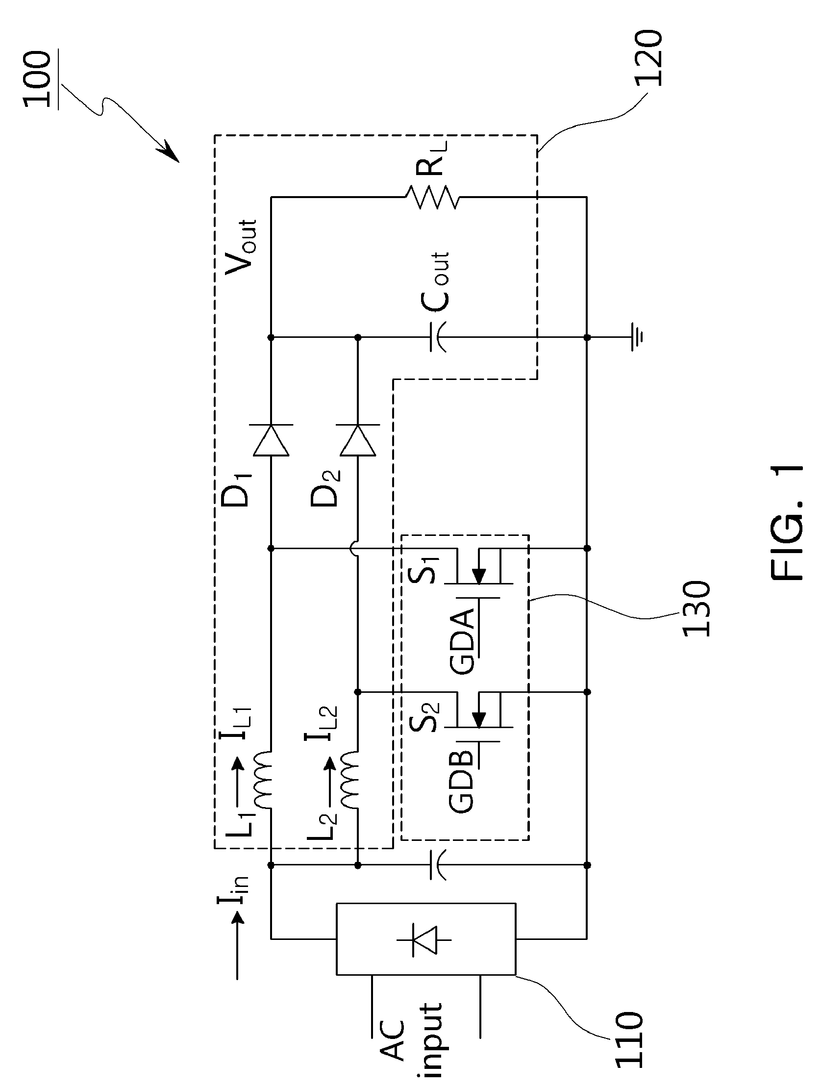
[0036]FIG. 1 is a schematic circuit diagram illustrating a power factor correction circuit according to an embodiment of the present invention.

[0037]Referring to FIG. 1, the power factor correction (PFC) circuit 100 according to the present embodiment may include a rectifying unit 110 receiving and rectifying alternating current (AC) power, a power factor correcting unit 120 including inductors L1 and L2 connected to each other in parallel, a resistor RL, and a capacitor C1OUT, and a switch unit 130 controlling an operation of circuits conn...


PUM


Abstract

There are provided a phase shift circuit and a power factor correction circuit including the same. The phase shift circuit includes a switching circuit unit charging power in or discharging power from a capacitor through a plurality of switching devices and comparing a voltage of the capacitor with a predetermined reference voltage, and a clock generating unit generating a reference clock signal based on an output of the switching circuit unit, wherein the switching circuit unit turns the plurality of switching devices on or off, based on currents from inductors respectively included in a main circuit and a sub-circuit of a power factor correction circuit to determine a polarity of the voltage of the capacitor.

Description

CROSS-REFERENCE TO RELATED APPLICATIONS[0001]This application claims the priority of Korean Patent Application No. 10-2012-0151303 filed on Dec. 21, 2012, in the Korean Intellectual Property Office, the disclosure of which is incorporated herein by reference.BACKGROUND OF THE INVENTION[0002]1. Field of the Invention[0003]The present invention relates to a phase shift circuit capable of significantly decreasing an electromagnetic interference (EMI) component of an input / output signal by adjusting a phase difference between driving signals of switches operating a main circuit and a sub-circuit included in a power factor correction circuit, and a power factor correction circuit including the same.[0004]2. Description of the Related Art[0005]Recently, in the electrical appliance and electronic device fields, research into a method of removing harmonic components generated in an input terminal of an electronic apparatus in order to significantly decrease an effect on a power line of an e...

Claims


Application Information

Patent Timeline
Patent Type & Authority Patents(United States)
IPC IPC(8): H02M1/42H02M1/14H02M3/158
CPCH02M1/4225H02M1/14H02M3/1584H02M2001/4291H02M2003/1586Y02B70/126Y02B70/10H02M1/4291H02M3/1586H02M1/12
Inventor JANG, YU JINCHO, HWANROH, YONG SEONGMOON, YOUNG JINPARK, JEONG PYOCHOI, JOONG HOYANG, JEONG MOYOO, CHANG SIK
Owner SKAICHIPS CO LTD
Features
  • R&D
  • Intellectual Property
  • Life Sciences
  • Materials
  • Tech Scout
  • Unparalleled Data Quality
  • Higher Quality Content
  • 60% Fewer Hallucinations
Learn More