Method and apparatus for placing a cannula in a bladder

a cannula and bladder technology, applied in the field of bladder cannula placement methods and devices, can solve the problems of engendering significant risks, difficult interior fascia layer, and requiring a considerable amount of pushing force for blunt force dilation, so as to avoid the risk of losing alignment, reduce the risk of enlargement of the small surgical pathway, and reduce the effect of enlargemen

Active Publication Date: 2016-03-01
SWAN VALLEY MEDICAL
View PDF119 Cites 1 Cited by
  • Summary
  • Abstract
  • Description
  • Claims
  • Application Information

AI Technical Summary

Benefits of technology

[0012]This invention involves a method and apparatus which are used very effectively to place a cannula through the abdominal wall and the bladder wall. An initial small surgical pathway, preferably made inside-out from the bladder through the bladder wall and the abdominal wall to the exterior skin, is expanded by outside-in force applied by an obturator, while the flaccid bladder wall is held firmly by reactive resistance created by fluid distention of the bladder. An effective seal within the bladder around the initial small surgical pathway is established before the obturator is used, thereby causing the distention fluid to offer enough reactive resistance to maintain the flaccid bladder wall in a firm condition conducive to blunt force dilation. The small pathway through the flaccid bladder wall is maintained in alignment with the small pathway through the firmer abdominal wall. With the bladder wall retained by the reactive resistance caused by fluid distention and with the small pathways through the bladder and abdominal walls in alignment, the small surgical pathway is effectively enlarged by an obturator around which a cannula is temporarily connected. The cannula is placed in the enlarged opening as a part of the same action which enlarges the small surgical pathway, thereby avoiding risks of losing alignment of the enlarged openings through the abdominal wall and the bladder wall if the cannula was inserted separately.
[0013]Penetration of the obturator through the internal fascia layer of the abdominal wall is achieved with the assistance from small cuts made by retractable blades at the forward end of the obturator. Substantial pushing force from the surgeon is not required, thereby avoiding risks that substantial pushing force may inadvertently damage adjoining internal organs or the opposite wall of the bladder. After penetrating the internal fascia layer, the small pathway through the bladder wall is expanded relatively easily by blunt force dilation while the flexible bladder wall is held firmly by the reactive resistance of the distending fluid within the bladder. The surgeon achieves enhanced control over the surgical procedure, which allows the surgical procedure to progress more rapidly with less trauma to the patient.
[0015]Additional features of this aspect of the invention involve some or all of the following. The small surgical pathway is enlarged into the enlarged opening by guiding an obturator along the placement guide and through the abdominal wall and the bladder wall. The obturator and the cannula are connected as a unit and guided along the placement guide and through the abdominal wall and the bladder wall. Cutting the exterior of the abdominal wall facilitates moving the unit-connected obturator and cannula through the exterior skin of the abdominal wall. Cutting the internal fascia layer of the abdominal wall by a blade which is selectively extended from a forward end of the obturator facilitates moving the obturator and cannula through the internal fascia layer. The opening through the bladder wall is expanded by blunt tip dilation after retracting the blade into the forward end of the obturator. The pulling tension on the placement guide is relaxed to allow the inflated placement balloon on the forward end of the placement guide to move out of contact with the bladder wall as the forward end of the obturator moves through the bladder wall. A stabilization balloon on the forward end of the cannula is inflated within the bladder and the cannula is withdrawn until the expanded stabilization balloon contacts of the bladder wall adjacent to the expanded opening. The obturator and placement guide are removed from within a conduit of the cannula after deflating the placement balloon on the forward end of the placement guide and disconnecting the obturator from the cannula. A retainer on the exterior of the conduit of the cannula contacts the abdominal wall at the enlarged opening while the expanded stabilization balloon contacts the bladder wall adjacent to the expanded opening, to maintain and stabilize the cannula within the expanded opening. The small surgical pathway through the bladder wall and the abdominal wall is preferably created by extending an advancement member from an end of a sound inserted through the urethra into the bladder, and the placement guide is extended through the small surgical pathway by connecting a forward end of the placement guide to a forward end of the advancement member and withdrawing the advancement member and the sound until the forward end of the placement guide is located in the bladder. The placement balloon is located in the bladder by severing the forward end of the placement guide from the forward end of the advancement member after both have been withdrawn through the urethra, and then returning the forward end of the placement guide into the bladder.

Problems solved by technology

Blunt force dilation usually requires a considerable amount of pushing force to create the enlarged opening.
A layer of mostly vascular and adipose tissue separates the exterior skin and the interior fascia layer in the abdominal wall, but this intermediate portion does not generally create substantial resistance to expansion.
However, making similar manual cuts the interior fascia layer is more difficult and engenders significant risks, because such cuts may extend beyond the internal fascia layer into adjacent internal organs and damage those organs.
Using trocars and obturators with cutting surfaces and blades carries the risk of unintended deeper penetration into and damage of adjoining internal organs.
Even with blunt tip trochars and obturators that do not have cutting surfaces or blades, there is a risk of damage to the adjacent internal organs.
Penetrating the bladder wall with a trocar or obturator is difficult because the bladder wall is very flaccid and easily deformable and movable.
The lack of significant reactive resistance from the bladder wall itself makes it is very difficult to penetrate the bladder wall from the outside to the inside of the bladder, which of course is the direction of penetration for enlarging the opening to insert the cannula.
However, making an initial small surgical pathway or incision through the bladder wall prior to expanding that small pathway causes the distention fluid to leak from the bladder, thereby losing most of the benefit derived from fluid distention.
However, if the initial alignment of the surgical pathway through the bladder wall and the abdominal wall is lost, as it will be if the advancement member which makes the inside-out initial small surgical pathway is withdrawn from that pathway, it is virtually impossible to regain the alignment of the small pathways through the bladder wall and the abdominal wall to facilitate enlarging the small pathway with outside-in blunt force dilation.
Thus, forming the initial small surgical pathway through the bladder wall does not facilitate enlargement of that opening, but instead may result in creating an extra opening through the bladder wall.
Even if the alignment of the initial surgical pathways through the bladder wall and abdominal wall is maintained, the flaccid nature of the bladder wall may cause it to deform in response to the blunt force from a trocar or obturator, thereby distorting the location of the enlarged opening in the bladder wall.

Method used


Image

  • Method and apparatus for placing a cannula in a bladder
  • Method and apparatus for placing a cannula in a bladder
  • Method and apparatus for placing a cannula in a bladder

Examples


Embodiment Construction

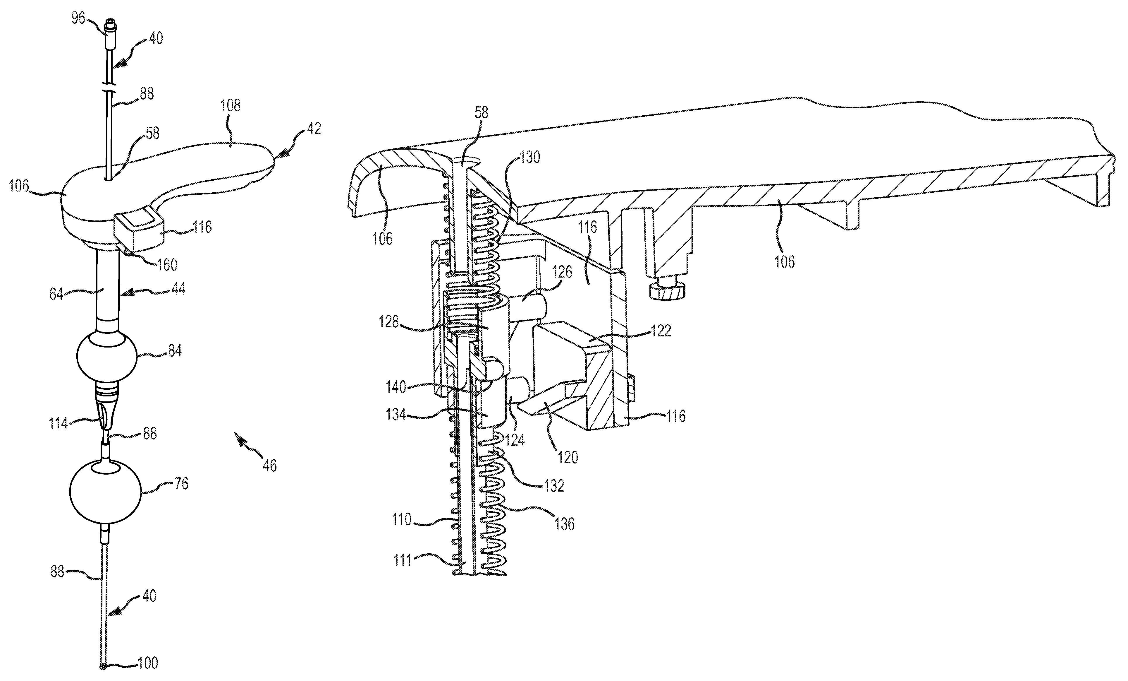
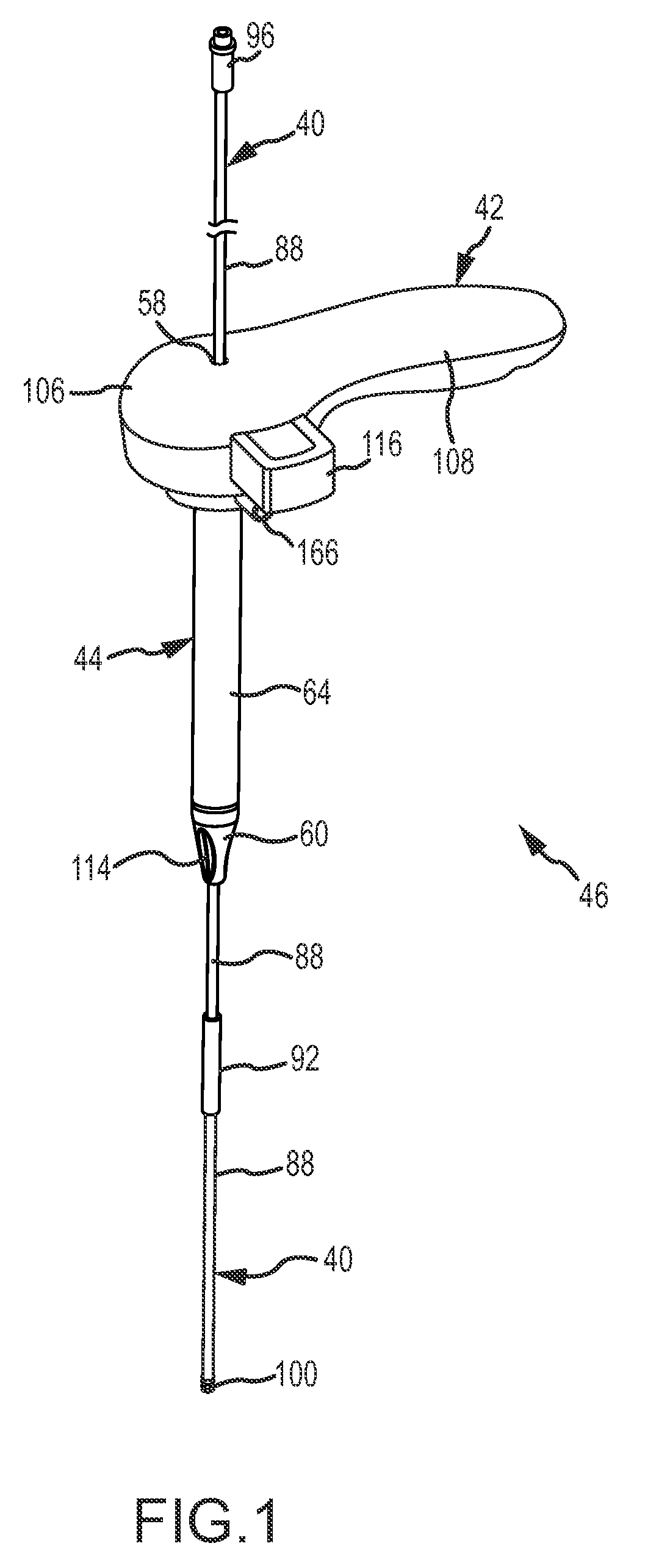
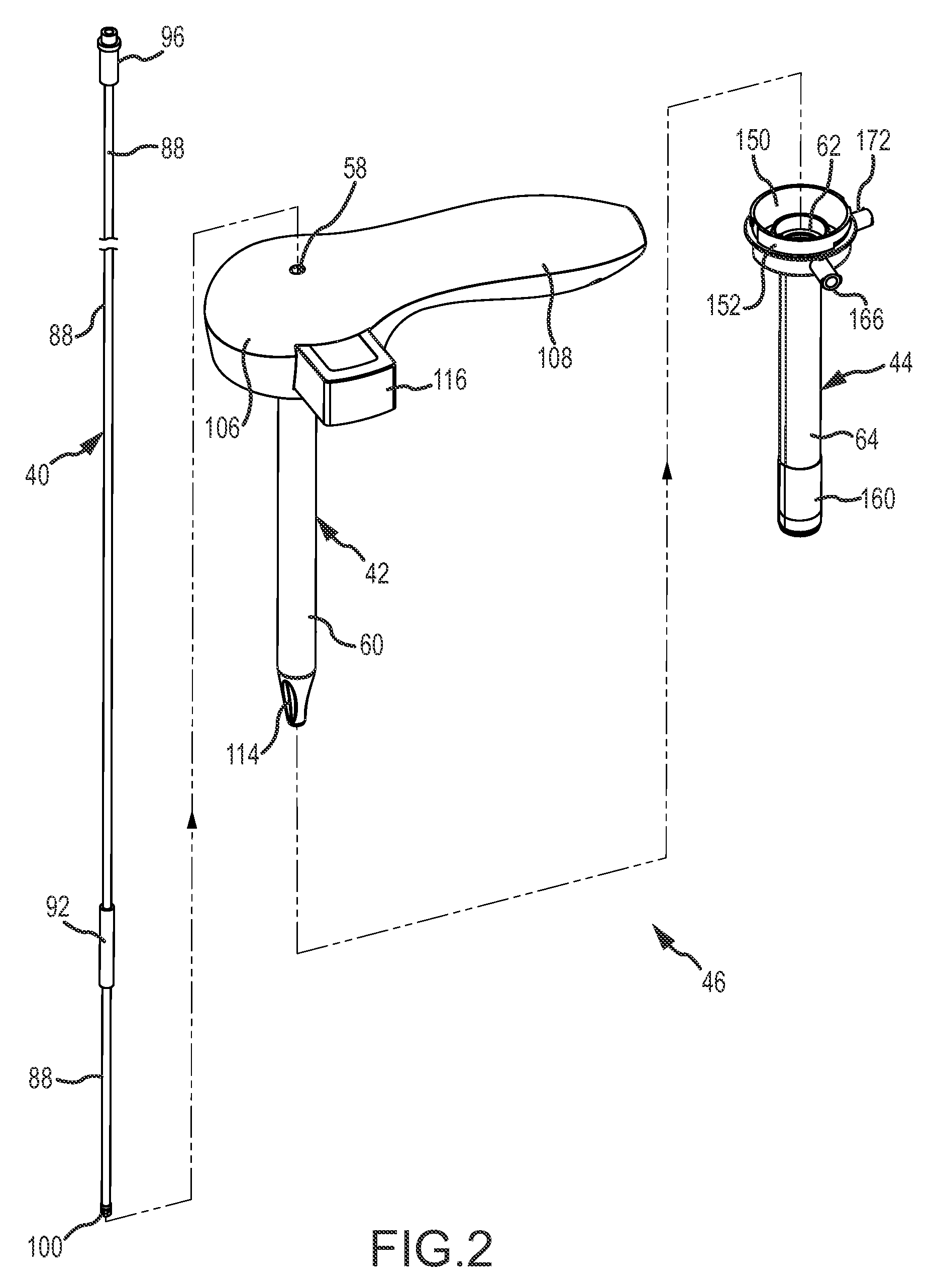
[0046]A placement guide 40, an obturator 42, and a cannula 44, shown generally in FIGS. 1-3, are used together as apparatus 46 to place the cannula 44 in an enlarged opening 48 (FIGS. 19-22) extending from a bladder 50 through a bladder wall 52 and an abdominal wall 54 of a living being, shown generally in FIGS. 10-22. Once placed in the enlarged opening 48, the cannula 44 provides access for inserting medical instruments 56 into the bladder 50 to perform a minimally invasive surgical procedure (FIG. 23).

[0047]To use the apparatus 46, the placement guide 40 is inserted within a center passage 58 of the obturator 42. A shaft of 60 of the obturator 42 is inserted within a central channel 62 of an exterior conduit 64 of the cannula 44. FIG. 1 shows the assembled relationship of the placement guide 40, the obturator 42 and the cannula 44, and FIG. 2 shows their interconnected relationship.

[0048]The enlarged opening 48 is formed from an initial small diameter surgical pathway 72 created ...


PUM


Abstract

A cannula is placed in an enlarged opening through a bladder wall and an abdominal wall by applying pulling tension to a placement guide extending through a small pathway to hold an inflated placement balloon in sealing contact with the bladder wall. The seal confines distension fluid in the bladder to establish sufficient reactive resistance to enlarge the opening through the bladder wall with blunt force dilation from an obturator.

Description

[0001]This invention relates to minimally invasive surgical procedures, and more particularly to such surgical procedures performed within a bladder of a living being. Even more particularly, the present invention relates to a new and improved method and apparatus for placing a cannula in the bladder by which to access the bladder to perform the surgical procedure. The method and apparatus significantly improve the reliability of placing the cannula in the bladder without inadvertently damaging adjoining organs and tissue, reduces the number of actions required by the surgeon, and facilitates progression of the procedure, among other things.BACKGROUND OF THE INVENTION[0002]Minimally invasive surgery is a surgical procedure performed by making a very small incision through which to insert surgical instruments to perform the surgical procedure. A minimally invasive procedure is usually performed in the abdominal region, by inserting a cannula through an abdominal wall of the patient. ...

Claims


Application Information

Patent Timeline
Patent Type & Authority Patents(United States)
IPC IPC(8): A61B17/34A61M29/02
CPCA61B17/3415A61B17/3403A61B17/3421A61M29/02A61B2017/3405A61B2017/346A61B2017/3486A61B17/0218A61B17/3423
Inventor ZOOK, RONALD, E.SAMPSON, LAURENCE, K.CARL, MARK
Owner SWAN VALLEY MEDICAL
Why Eureka
Try Eureka