Soundproofing cladding panel, and an aircraft

a technology of soundproofing and cladding, applied in the field of soundproofing cladding panels, can solve the problems of increasing the sound level of noise, problems encountered, and the technical field of aircraft, and achieve the effect of reducing the weigh

Active Publication Date: 2016-03-01
EUROCOPTER
View PDF17 Cites 0 Cited by
  • Summary
  • Abstract
  • Description
  • Claims
  • Application Information

AI Technical Summary

Benefits of technology

[0049]An object of the present invention is to propose a self-supporting panel of minimized weight that is acoustically insulating.

Problems solved by technology

Reducing the sound level of noise is a problem that is increasing because of the impacts of noise on people's comfort and health.
This problem is encountered, particularly but not exclusively, in the technical field of aircraft, and in particular of rotary wing aircraft.
Thus, an aircraft generally has multiple sources of noise, e.g. including one or more rotors, a main gearbox, and blades of turboshaft engines or indeed of fans.
Furthermore, the panels that are obtained are relatively light in weight, given that weight is usually an important parameter for an aircraft.
Nevertheless, such a cladding panel made of composite materials may present a fabrication cost that is relatively high.
A manufacturer is then confronted with a difficult choice for optimizing the sound comfort of an occupant of an aircraft.
Nevertheless, such a panel runs the risk of not having sufficient mechanical strength to be self-supporting.
If the manufacturer selects the first known embodiment for the purpose of stiffening the panel, the manufacturer then obtains a panel that is more expensive and that runs the risk of having a critical frequency that is troublesome.
Fabricating a cladding panel can thus involve a compromise that is difficult to resolve in satisfactory manner.
Nevertheless, it can be difficult to implement panels of the same type as the above-described second known embodiment.
The cost of producing such a panel may also be relatively high.

Method used


Image

  • Soundproofing cladding panel, and an aircraft
  • Soundproofing cladding panel, and an aircraft
  • Soundproofing cladding panel, and an aircraft

Examples


Embodiment Construction

[0121]Elements present in more than one of the figures are given the same references in each of them.

[0122]It should be observed that three mutually orthogonal directions X, Y, and Z are shown in some of the figures.

[0123]The direction X is said to be longitudinal and another direction Y is said to be transverse. Finally, a third direction Z is said to be in elevation and corresponds to the height dimensions of the structures described. The term “thickness” then relates to a dimension in elevation of the device in this elevation direction.

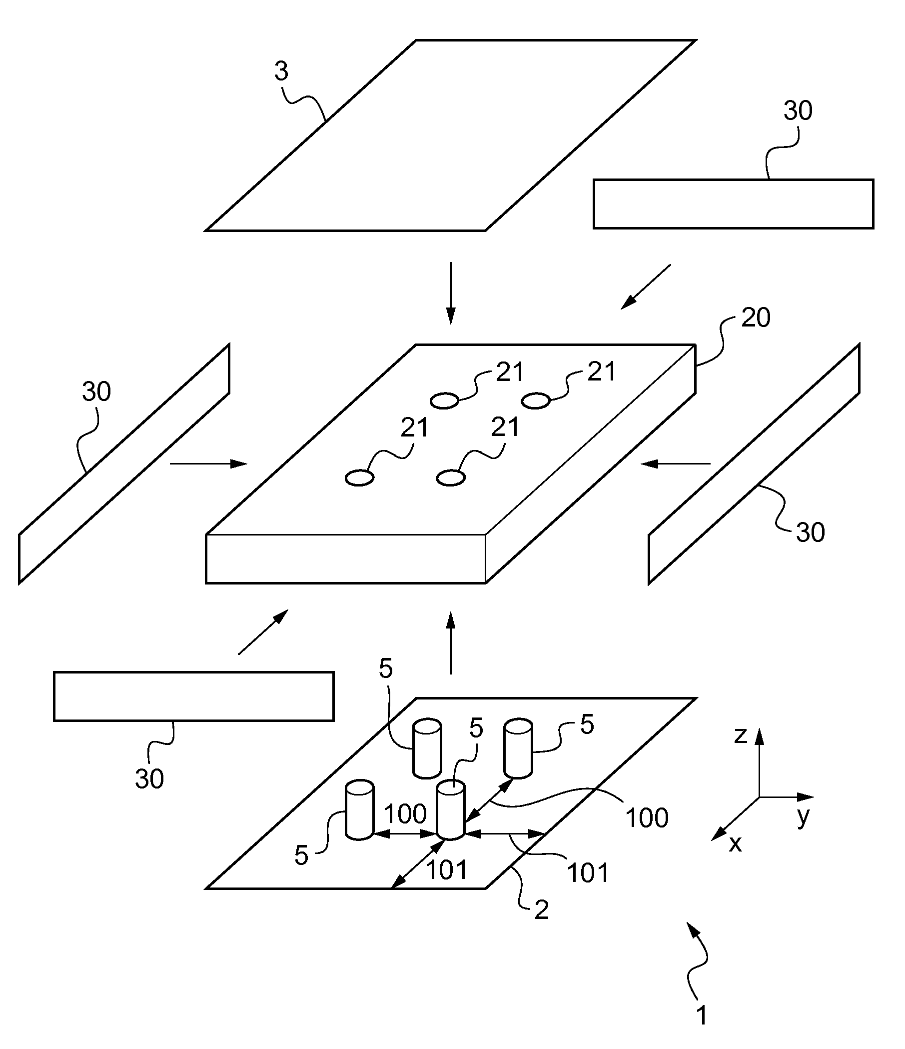
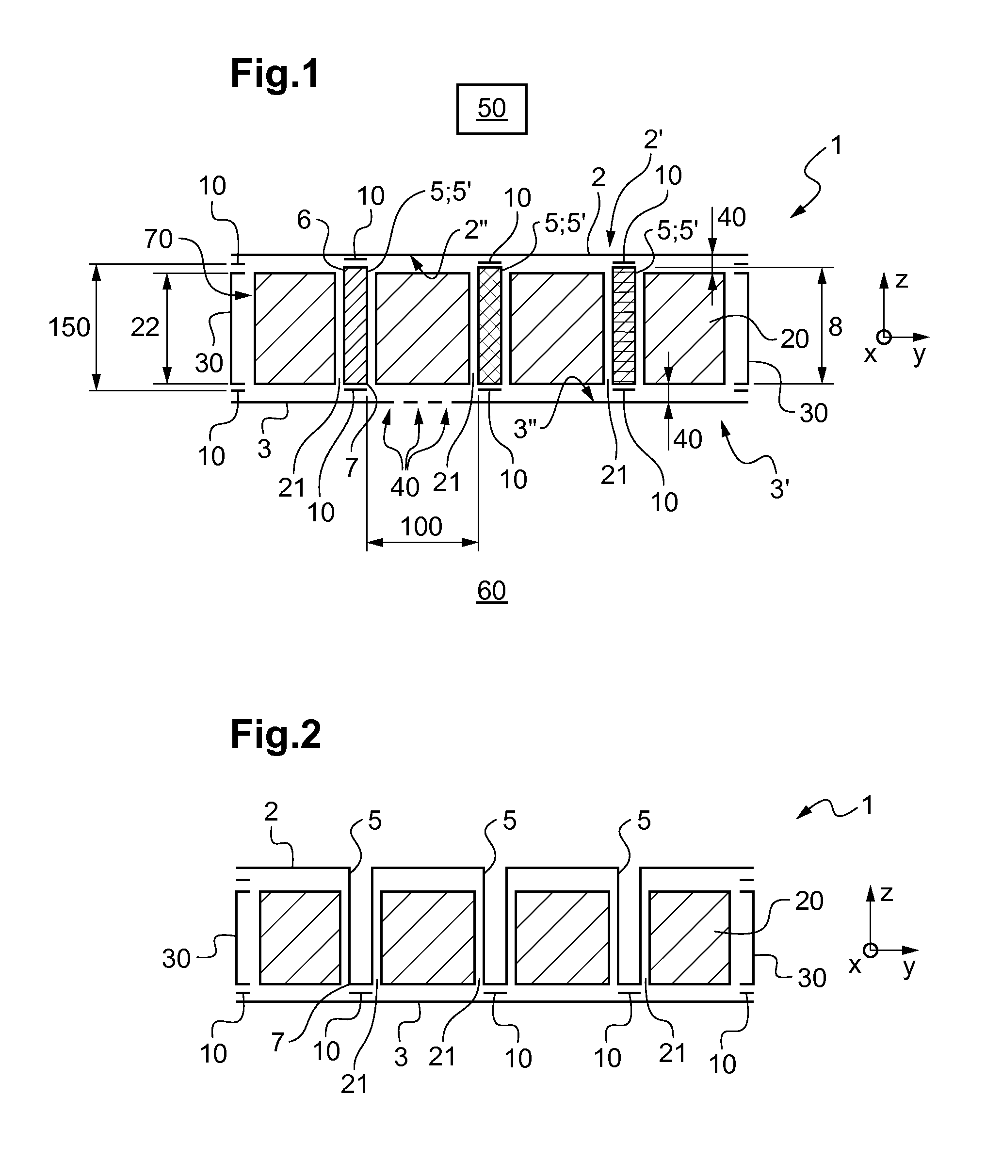
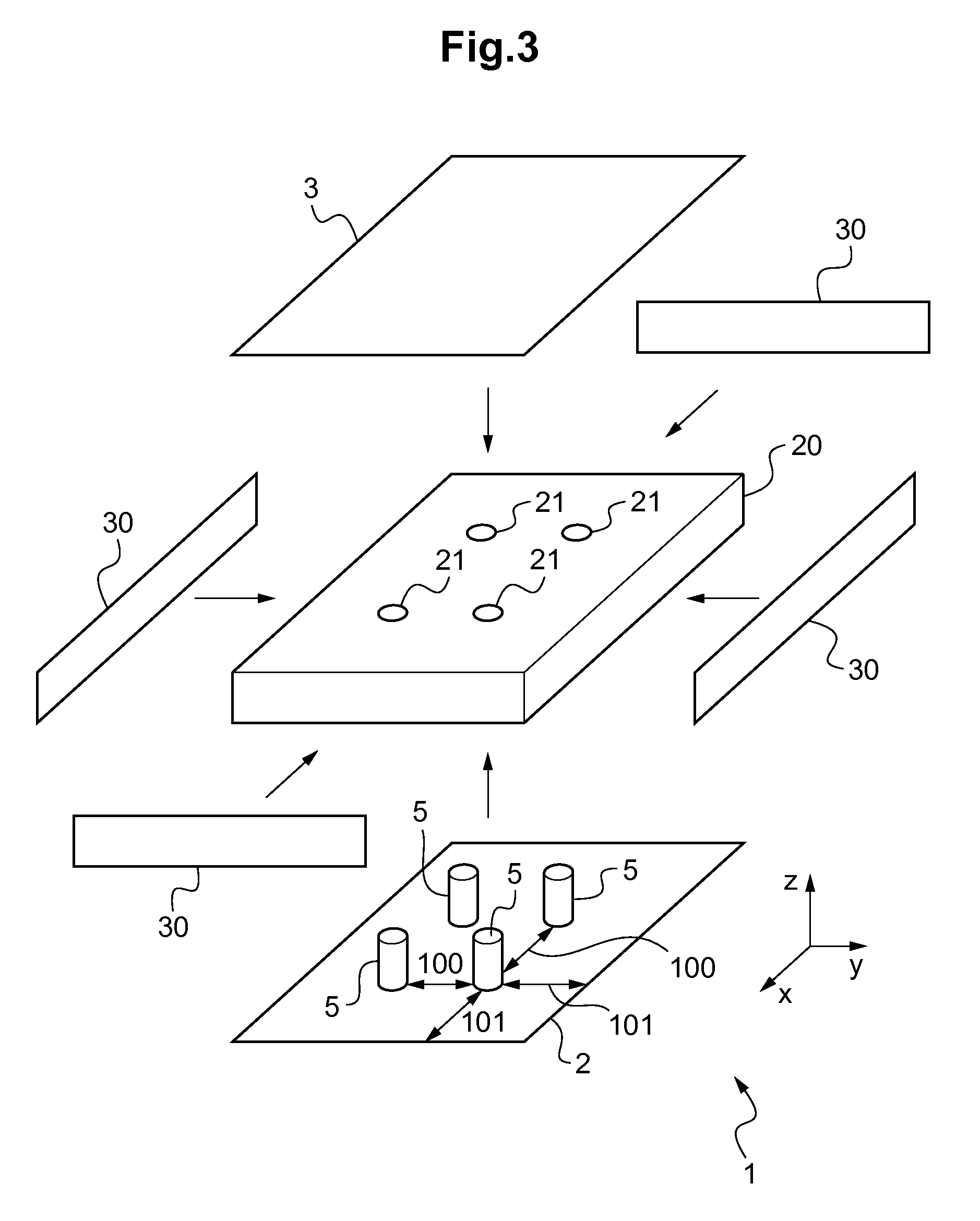
[0124]FIG. 1 shows an aircraft having a panel 1. The other members of the aircraft are not shown in order to avoid pointlessly cluttering the figure.

[0125]The panel 1 has a wall referred to as an “invisible” wall 2 and another wall referred to as a “visible” wall 3.

[0126]Under such circumstances the invisible wall 2 faces a noise source 50, whereas conversely the visible wall 3 faces a location 60 that is to be acoustically insulated from the noise...


PUM

PropertyMeasurementUnit
frequencyaaaaaaaaaa
frequencyaaaaaaaaaa
frequenciesaaaaaaaaaa

Abstract

A self-supporting acoustic insulation panel (1) comprising a visible wall (3) that is not self-supporting and an invisible wall (2) that is not self-supporting facing a source (50) of soundwaves. A porous core (20) is arranged between the visible wall (3) and the invisible wall (2), a plurality of link elements (5) each extending from the invisible wall (2) towards the visible wall (3), each link element (5) passing through an orifice (21) in said core (20) and being connected to the visible wall (3) and to the invisible wall (2), each link element (5) separating the visible wall (3) from the invisible wall (2) and mechanically linking the visible wall (3) with the invisible wall (2) while acoustically decoupling the visible wall (3) from the invisible wall (2).

Description

CROSS REFERENCE TO RELATED APPLICATION[0001]This application claims priority to French patent application No. FR 13 02736 filed on Nov. 26, 2013, the disclosure of which is incorporated in its entirety by reference herein.BACKGROUND OF THE INVENTION[0002](1) Field of the Invention[0003]The present invention relates to a soundproofing cladding panel, and to an aircraft including such a panel.[0004]The invention is thus situated in the field of treating acoustic nuisance on board an aircraft.[0005](2) Description of Related Art[0006]The present invention relates more particularly to systems for treating noise. Reducing the sound level of noise is a problem that is increasing because of the impacts of noise on people's comfort and health. This problem is encountered, particularly but not exclusively, in the technical field of aircraft, and in particular of rotary wing aircraft.[0007]A rotary wing aircraft comprises at least one lift rotor that is driven in rotation by a drive train. Th...

Claims


Application Information

Patent Timeline
Patent Type & Authority Patents(United States)
IPC IPC(8): B64C1/40G10K11/168B32B7/04B32B3/26
CPCB64C1/40B32B3/266B32B7/045G10K11/168B32B2307/102B32B5/022B32B5/18B32B7/12B32B27/065B32B27/12B32B27/20B32B27/281B32B27/32B32B27/34B32B27/365B32B27/38B32B27/40B32B2262/101B32B2262/103B32B2262/106B32B2266/06B32B2605/18B32B7/05
Inventor CAILLET, JULIENSIBOIS, HELENEFABRIZIO, JEAN-PIERREKNOR, EGLE
Owner EUROCOPTER
Why Eureka
Try Eureka