Supercharge Your Innovation With Domain-Expert AI Agents!

Metal hose fitting and flanged insert that safely conducts high velocity fluids/gases up to Mach 1

a technology of flange insert and hose fitting, which is applied in the direction of hose connection, machine/engine, mechanical apparatus, etc., can solve the problems of reduced flow, excessive noise, and turbulence at the junction of the liner and the end fitting, so as to reduce turbulence and reduce turbulence in the hose

Active Publication Date: 2016-03-01
DELAFIELD CORP
View PDF28 Cites 10 Cited by
  • Summary
  • Abstract
  • Description
  • Claims
  • Application Information

AI Technical Summary

Benefits of technology

The present invention provides a metal hose design for high-speed gas or liquid applications. It includes a flanged metal insert and a lead-in pipe with a tapered interior wall which, when used together, improve the performance of corrugated metal hose. The flanged insert protects the hose and welds from vibrations, while the lead-in pipe creates a smooth flow and prevents abrasion of the liner. The invention combines these features to provide a better, more efficient hose design for high-speed applications.

Problems solved by technology

This circumference at the junction of the liner to the end fitting is also subject to turbulence.
This turbulence can result in excessive noise, reduced flow, or even catastrophic failure due to metal fatigue.

Method used


Image

  • Metal hose fitting and flanged insert that safely conducts high velocity fluids/gases up to Mach 1
  • Metal hose fitting and flanged insert that safely conducts high velocity fluids/gases up to Mach 1
  • Metal hose fitting and flanged insert that safely conducts high velocity fluids/gases up to Mach 1

Examples


Embodiment Construction

[0048]Although specific embodiments of the present invention will now be described with reference to the drawings, it should be understood that such embodiments are by way of example only and merely illustrative of but a small number of the many possible specific embodiments which can represent applications of the principles of the present invention. Various changes and modifications obvious to one skilled in the art to which the present invention pertains are deemed to be within the spirit, scope and contemplation of the present invention as further defined in the appended claims.

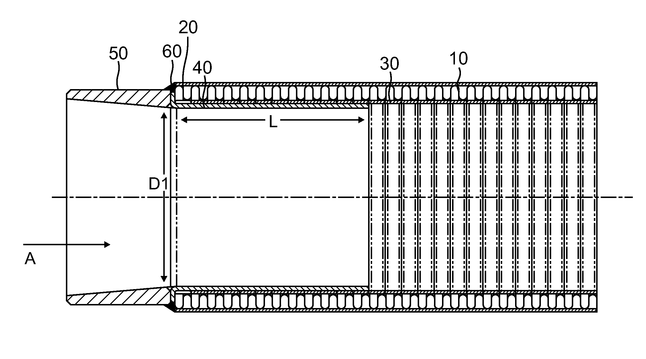
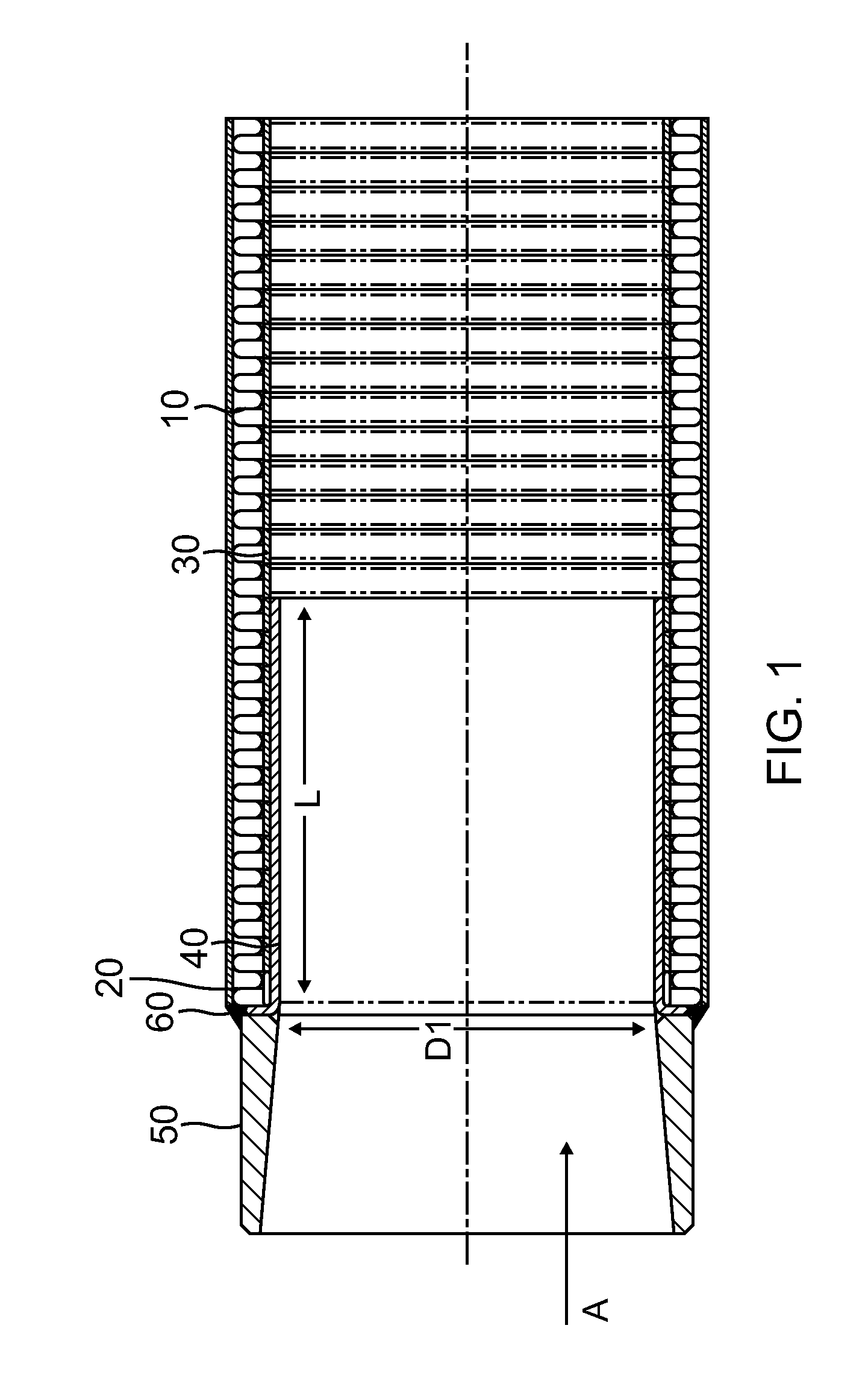
[0049]Referring to the general concept of the present invention illustrated in FIG. 1 the present invention is a metal hose in cross-section 10 which is covered by a braid 20 which hose 10 in turn covers an interior liner 30 of the hose. The hose is used to conduct high velocity fluids and gases up to Mach 1. The invention has the following additional improvements:

[0050]1. The invention includes the insert...


PUM


Abstract

An apparatus to enable the flow of high speed gases through the apparatus, the apparatus including modifying a metal hose which can be a metal hose or a corrugated metal hose having an exterior braid and an interior liner. The improvement includes inserting a non-bendable flange insert into a leading edge of the metal pipe and combining that with a pipe having a tapered interior wall which is welded to the metal hose to facilitate the flow of gases to a level of Mach 1 without damaging the interior portions of the interior liner.

Description

BACKGROUND OF THE INVENTION[0001]1. Field of the Invention[0002]The present invention relates to field of metal hose designs which are subjected to high velocity gasses passing into and through the hose.[0003]2. Description of the Prior Art[0004]The following ten patents and published patent applications are relevant to the present invention:[0005]1. U.S. Pat. No. 4,991,876 issued to Philip Mulvey on Feb. 12, 1991 for “Connector Assembly For Hot Water Heaters And Other Appliances” (hereafter the “Mulvey Patent”);[0006]2. U.S. Pat. No. 5,890,748 issued to Daniel Phillips et al. on Apr. 6, 1999 for “Composite Male Hose Coupler” (hereafter the “Phillips Patent”);[0007]3. U.S. Pat. No. 6,660,199 issued to Roger Lee Siferd et al. on Dec. 9, 2003 for “Pipe Structure And Method of Manufacture” (hereafter the “Siferd Patent”);[0008]4. U.S. Pat. No. 6,866,302 issued to Norihiko Furata on Mar. 15, 2005 for “Connecting Structure For Hose With Corrugated Metal Tube” (hereafter the “Furata Paten...

Claims


Application Information

Patent Timeline
Patent Type & Authority Patents(United States)
IPC IPC(8): F16L33/01
CPCF16L33/01F01N13/1816F16L51/025F16L51/026F16L51/027F01N2450/22F01N2470/12F01N2470/24F01N2530/04F01N2530/26
Inventor MARTIN, JAMES
Owner DELAFIELD CORP
Features
  • R&D
  • Intellectual Property
  • Life Sciences
  • Materials
  • Tech Scout
  • Unparalleled Data Quality
  • Higher Quality Content
  • 60% Fewer Hallucinations
Learn More