Wood burning furnace

Inactive Publication Date: 2016-03-01
OREILLY PAUL D
View PDF55 Cites 1 Cited by
  • Summary
  • Abstract
  • Description
  • Claims
  • Application Information

AI Technical Summary

Benefits of technology

[0006]In normal operation with the door leading into the primary combustion chamber closed air is brought into the air box and forced downwardly through the aperture between the air box and primary combustion chamber through the wood storage box/primary combustion chamber containing a wood fire with a bed of coals being fed with fresh fuel from above. The wood fire releases smoke, particulates, combustibles and other volatile gases through the ash grate into the secondary combustion chamber. The wood combustion in the primary combustion chamber results in gasification of the wood fuel through the ash grate and combustion of the gas and residual particulates in the secondary combustio

Problems solved by technology

This arrangement, although effective for producing heat, has drawbacks relating to loading wood into the primary combustion chamber and power failures.
The '959 damper arrangement has a tendency to generate smoke from the combustion chambers back into the ambient area about the furnace.
When there is a power failure, both air box d

Method used


Image

  • Wood burning furnace
  • Wood burning furnace
  • Wood burning furnace

Examples


Embodiment Construction

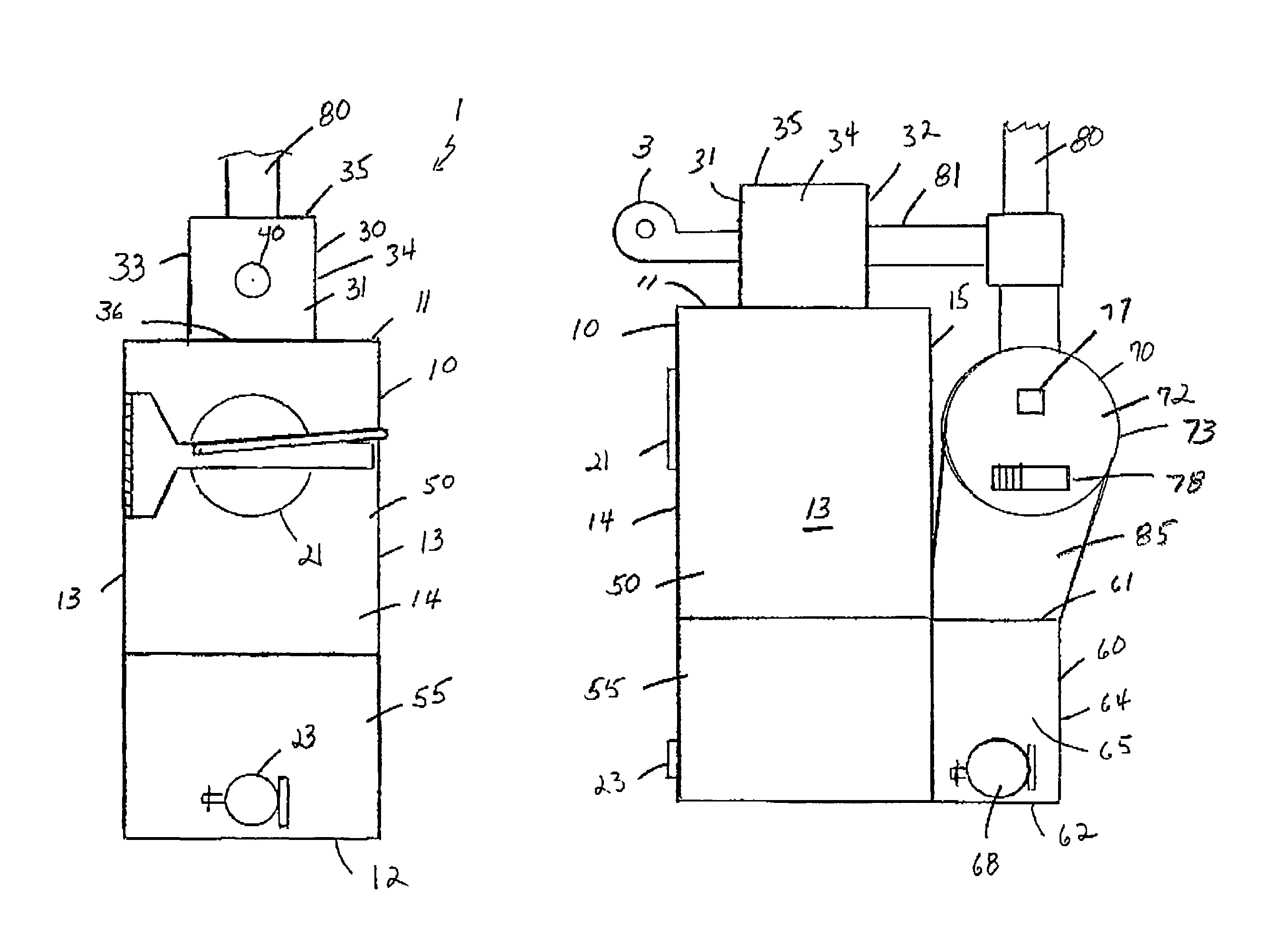
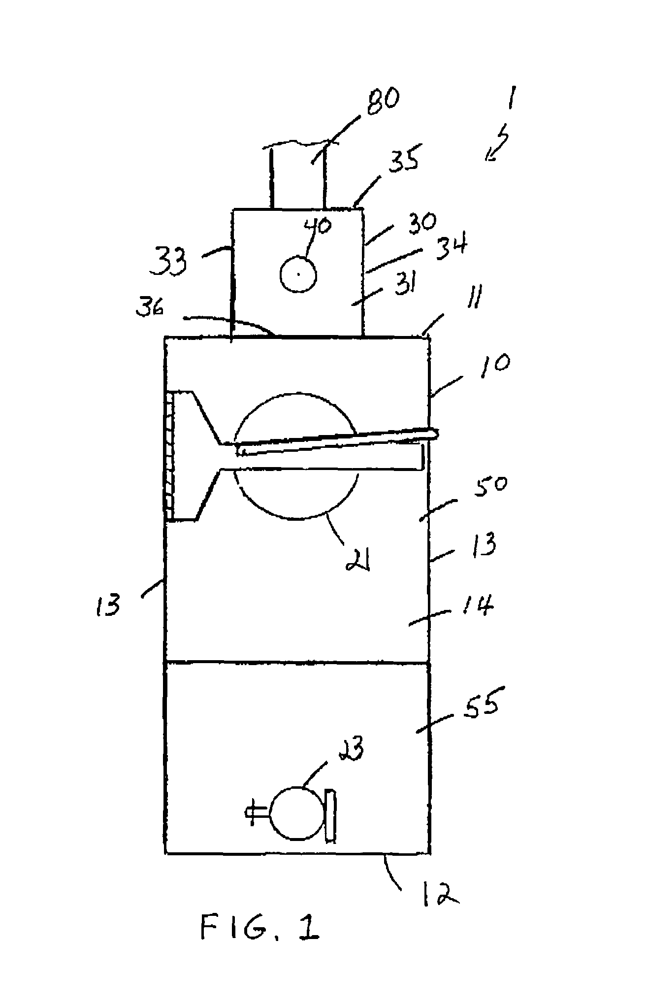
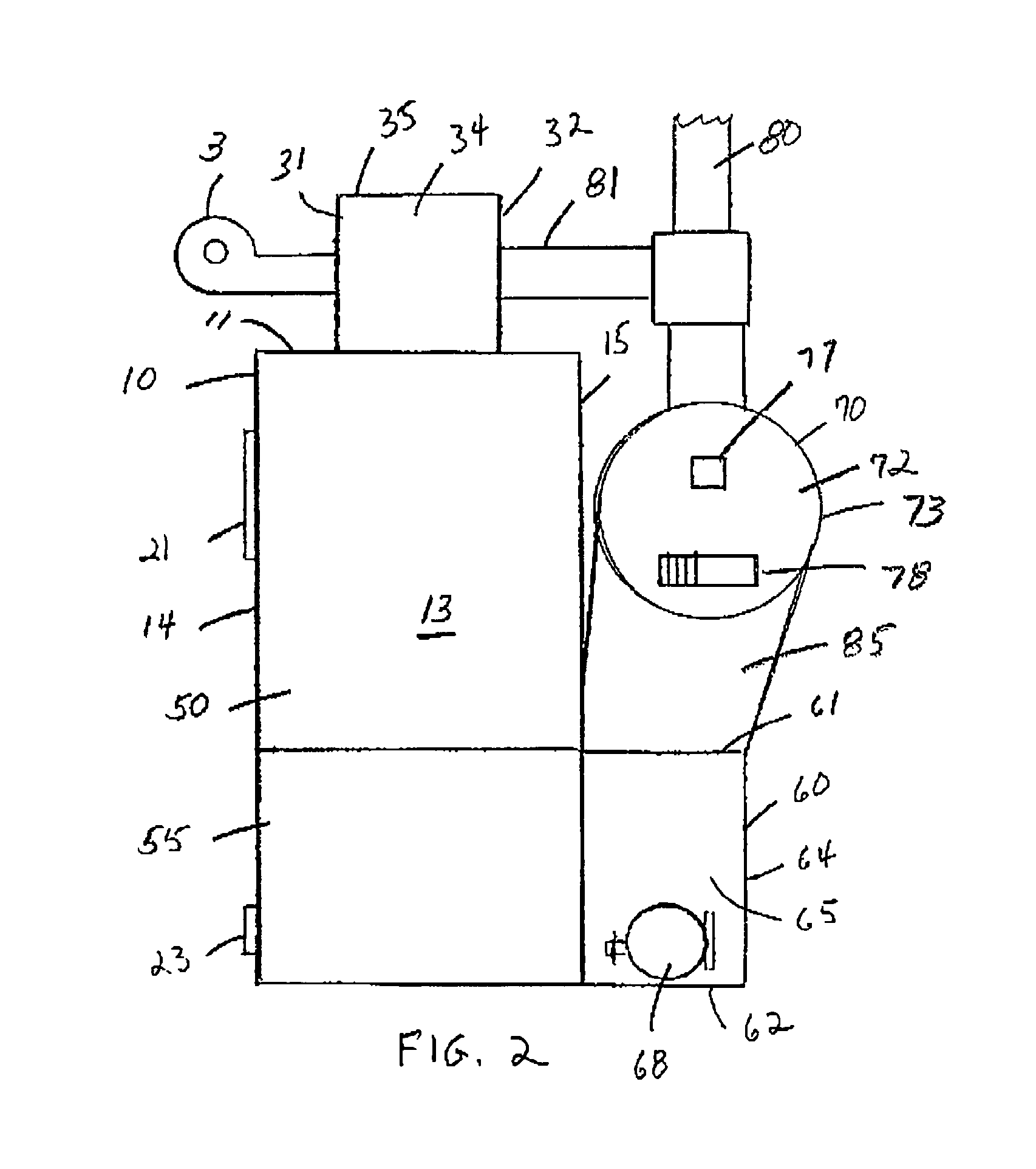
[0029]Referring to the drawings in detail wherein like elements are indicated by like numerals, there is shown a wood burning furnace 1 constructed according to the principles of the present invention. The furnace 1 has a firebox 10 having a top 11, a bottom 12, two opposite sides 13, a front 14, and a rear 15, said top, bottom, sides, front and rear defining a firebox interior 16. The furnace 1 is further comprised of an air box 30 connected to the firebox top 11, a manifold chamber 60 connected to the firebox rear 15 near to the firebox bottom 12. The manifold chamber 60 is attached to a heat exchanger 70 with an outlet to a furnace exhaust flue 80.

[0030]The air box 30 has a generally rectangular shape, but other invention embodiments may have different shapes. The air box 30 has a front wall 31, rear wall 32, a left side wall 33, a right side wall 34, a top 35, and a bottom 36, said walls, top and bottom defining a hollow air box interior 37. The air box bottom 36 is attached to ...


PUM


Abstract

A wood burning furnace providing, in sequential connection, an air box, a fire box with a wood storage box/primary combustion chamber and a secondary combustion chamber separated by an ash grate, a heat exchanger, an exhaust manifold, and a smoke stack. The air box has an input port attached to an intake air blower. The air box also has two dampers, a first damper providing controlled access to an updraft exhaust pipe connected to the smoke stack. The second damper provides controlled access from the intake blower through the air box to the wood storage box/primary combustion chamber.

Description

BACKGROUND OF THE INVENTION[0001]This invention relates to furnaces, and more particularly to wood-burning, downdraft furnace.[0002]A simple wood-burning furnace usually comprises a metal box having a door for loading wood, an air inlet control system (often part of the door) for controlling the amount of combustion air admitted into the box and an exhaust flue for directing exhaust gases from the box. Such simple wood burning stoves tend to be inefficient because unburned vapors and particulates pass out of the exhaust flue. Admitting more combustion air may reduce the amount of unburned vapors and particulates passed out of the exhaust flue, but then the fire tends to burn too hot and too fast.[0003]A solution to such problems is to make the wood-burning furnace a downdraft furnace. Downdraft furnaces promote “secondary combustion.” Primary combustion is throttled by controlling the amount of combustion air. The unburned vapors and particulates are then mixed with heated air in a ...

Claims


Application Information

Patent Timeline
IPC IPC(8): F24B5/00F24B5/02
CPCF24B5/026F24B5/023F24B5/028F23B50/06F24B5/04F24B7/045
Inventor O'REILLY, PAUL, D.
Owner OREILLY PAUL D
Why Eureka
Try Eureka