Internal combustion engine

a combustion engine and combustion chamber technology, applied in the direction of electrical control, process and machine control, instruments, etc., can solve the problems of increasing the amount of discharged unburned fuel, inevitably generated nitrogen oxides (nox), limited etc., to achieve high temperature combustion, reduce emissions, and reduce the leanness of hydrogen-air mixtur

Inactive Publication Date: 2009-02-12
NISSAN MOTOR CO LTD
View PDF1 Cites 73 Cited by
  • Summary
  • Abstract
  • Description
  • Claims
  • Application Information

AI Technical Summary

Benefits of technology

[0005]The leanness of the hydrogen-air mixture is limited due to the fact that ignition must be performed reliably by the spark plug. Accordingly, the hydrogen concentration of the hydrogen-air mixture is set comparatively high to achieve high temperature combustion. As a result, nitrogen oxides (NOx) are generated inevitably during combustion of the hydrogen-air mixture. Furthermore, the homogeneous air-fuel mixture in the unburned region is compressed by the combustion expansion of the hydrogen-air mixture so as to self-ignite sequentially from the location of an ignition point. The homogeneous air-fuel mixture cannot be caused to self-ignite at the same time throughout the entire combustion chamber. During a low load period of the engine in particular, self-ignition cannot be generated in a region in the vicinity of a cylinder wall surface, and therefore the amount of discharged unburned fuel increases.
[0006]It is therefore an object of this invention to provide an internal combustion engine that can achieve a reduction in emissions while realizing high thermal efficiency through self-ignition combustion.

Problems solved by technology

Therefore problems such as the following arise in relation to emissions.
The leanness of the hydrogen-air mixture is limited due to the fact that ignition must be performed reliably by the spark plug.
As a result, nitrogen oxides (NOx) are generated inevitably during combustion of the hydrogen-air mixture.
During a low load period of the engine in particular, self-ignition cannot be generated in a region in the vicinity of a cylinder wall surface, and therefore the amount of discharged unburned fuel increases.

Method used


Image

  • Internal combustion engine
  • Internal combustion engine
  • Internal combustion engine

Examples


first embodiment

[0029]Referring to FIG. 1-FIG. 6, this invention will be described.

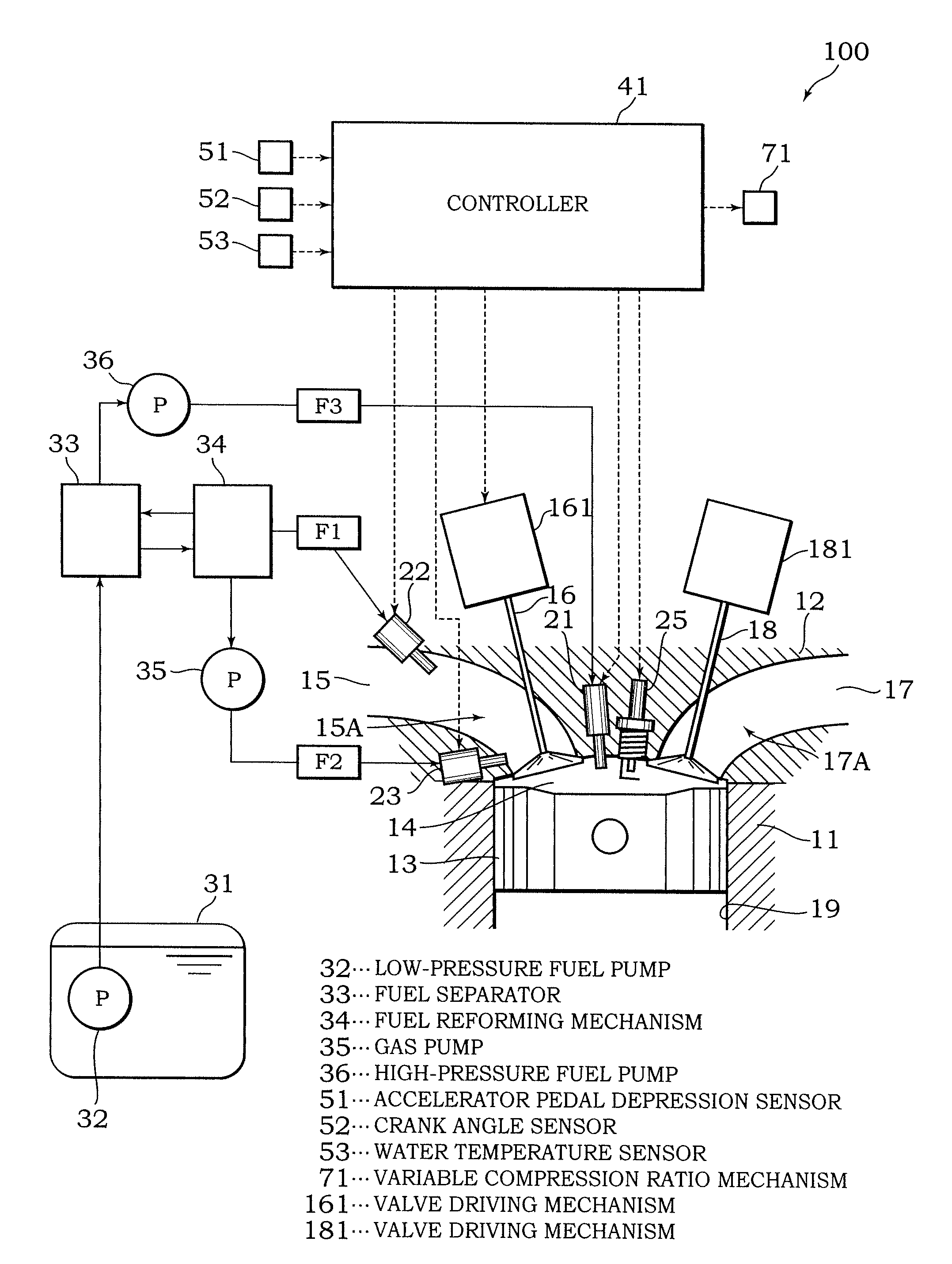
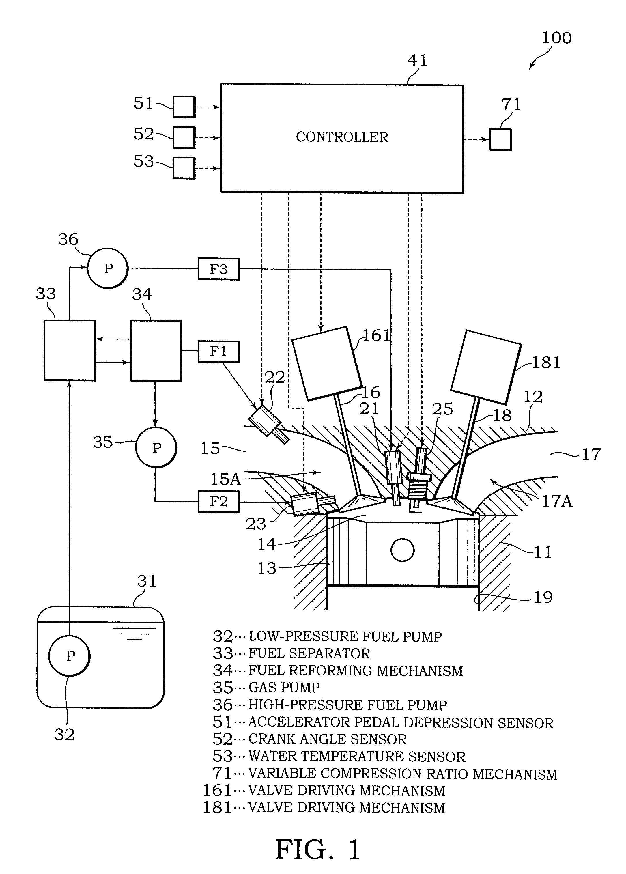
[0030]Referring to FIG. 1, an internal combustion engine 100 for a vehicle comprises a cylinder block 11, and a cylinder head 12 disposed on an upper side of the cylinder block 11.

[0031]A cylinder 19 housing a piston 13 is formed in the cylinder block 11. A combustion chamber 14 is formed by a wall surface of the cylinder 19, a crown surface of the piston 13, and a lower surface of the cylinder head 12. When an air-fuel mixture is burned in the combustion chamber 14, the piston 13 receives combustion pressure and reciprocates through the interior of the cylinder 19.

[0032]An intake port 15A that communicates with an intake passage 15 and opens onto one side of the combustion chamber 14 is formed in the cylinder head 12. An intake valve 16 is provided in the intake port 15A. When the intake valve 16 is open, air from which dust particles and the like have been removed by an air cleaner is aspirated into the combustion ...

second embodiment

[0069]Referring to FIG. 9-FIG. 14, this invention will be described.

[0070]The internal combustion engine 100 according to this embodiment differs from the first embodiment in the constitutions of the combustion chamber, fuel system, and the content of control thereof. Other constitutions of the internal combustion engine 100 are identical to their counterparts in the first embodiment.

[0071]Referring to FIG. 9, the internal combustion engine 100 comprises a main combustion chamber 141 defined by the wall surface of the cylinder 19, the cylinder head 12 and the piston 13, and a fixed-volume auxiliary combustion chamber 142 separated from the main combustion chamber 141 and connected thereto via injection holes 142A. The auxiliary combustion chamber 142 forms a flame torch that spouts out the main combustion chamber 141 through each of the injection holes 142A when an air-fuel mixture in the auxiliary combustion chamber 142 is burned.

[0072]The internal combustion engine 100 comprises t...

third embodiment

[0100]Referring to FIG. 15, FIG. 16, FIGS. 17A and 17B, and FIGS. 18A and 18B, this invention will be described.

[0101]The internal combustion engine 100 according to this embodiment is substantially identical to that of the first embodiment, but differs therefrom in that the controller 41 performs fuel injection control such that combustion in the low load / low rotation speed region A is further stabilized. More specifically, the injection amounts of the respective fuels are corrected in accordance with the combustion condition of the air-fuel mixture, and the following description will center on this difference.

[0102]Referring to FIG. 15, the internal combustion engine 100 comprises a cylinder pressure sensor 54 and a knocking level sensor 55.

[0103]The cylinder pressure sensor 54 is provided in the cylinder block 11 to detect the internal pressure of the combustion chamber 14. A detection signal from the cylinder pressure sensor 54 is input into the controller 41.

[0104]The knocking ...


PUM


Abstract

An internal combustion engine (100) comprises a fuel injection valve (21, 22) which supplies a first fuel having a higher self-ignitability than gasoline and a second fuel having a higher combustion speed than gasoline such that an air-fuel mixture containing the first fuel and the second fuel is formed in a combustion chamber (14), a spark plug (25) which ignites the air-fuel mixture, and a programmable controller (41) programmed to control supply proportions of the first fuel and the second fuel such that the ignited air-fuel mixture undergoes flame propagation combustion and then undergoes self-ignition combustion. Thus, a reduction in emissions can be achieved, and high thermal efficiency can be realized through the self-ignition combustion.

Description

FIELD OF THE INVENTION[0001]This invention relates to an internal combustion engine that performs premixed compression ignition combustion.BACKGROUND OF THE INVENTION[0002]JP2004-036538A, published by the Japan Patent Office in 2004, discloses an internal combustion engine that causes an air-fuel mixture to undergo compression ignition combustion (self-ignition combustion).[0003]The internal combustion engine according to the prior art forms a homogeneous air-fuel mixture of gasoline in a combustion chamber. The internal combustion engine then injects hydrogen gas, which has a comparatively high octane value and does not self-ignite easily, in the vicinity of top dead center of a compression stroke to form a hydrogen-air mixture on the periphery of a spark plug. The hydrogen-air mixture is subjected to spark ignition combustion by the spark plug, and homogeneous air-fuel mixture in an unburned region is compressed as a result of combustion expansion of the hydrogen-air mixture so as...

Claims


Application Information

Patent Timeline
Patent Type & Authority Applications(United States)
IPC IPC(8): F02D41/30
CPCF02D13/02F02D19/0692F02D19/081F02D35/023F02D35/027F02D41/0025F02D41/0027F02D2200/1015Y02T10/12Y02T10/18Y02T10/36F02D19/061F02D19/0644F02D19/0671F02D19/0689F02D15/00Y02T10/30
Inventor NODA, TORUTERAJI, ATSUSHIARAKI, TAKASHIKAKUHO, AKIHIKOHOTTA, ISAMUASHIDA, KOICHIKASSAI, MASAHARU
Owner NISSAN MOTOR CO LTD
Why Eureka
Try Eureka