
Device for turning over and conveying an object

a technology for turning over objects and conveying objects, which is applied in the directions of transportation and packaging, pile separation, packaging, etc., can solve the problems of requiring additional complicated components, requiring complicated mounting of stationary transportation devices, and affecting the effect of reducing the energy consumption of turning over objects

Active Publication Date: 2016-03-15
WINDMOELLER & HOELSCHER GMBH
View PDF29 Cites 7 Cited by
  • Summary
  • Abstract
  • Description
  • Claims
  • Application Information

AI Technical Summary

Benefits of technology

The invention is a rotary drive system that can drive both sides of a frame using a single rotary drive. This means that the drive can increase the speed of the frame without needing heavier connection elements. The system uses two gear elements to rotate the rotary disks, which can be connected to the frame using reliable transport elements. The rotary drive can also have two flat, toothed, or v-ribbed belts to transmit the action of the gear elements to the rotary disks, ensuring even distribution of power. This design is lighter, more stable, and reduces energy consumption at higher speeds.

Problems solved by technology

In this case, it has proven disadvantageous that the transport of the objects is delayed.
In addition, the stationary transport device requires a complicated mounting in order to drive the transport elements, and to cushion the movement of the transport elements toward the transport drive.
Furthermore, additional complicated components are required to obtain a detachable connection between the transport elements and the transport drive, generally by means of a friction-fit connection.

Method used


Image

  • Device for turning over and conveying an object
  • Device for turning over and conveying an object
  • Device for turning over and conveying an object

Examples


Embodiment Construction

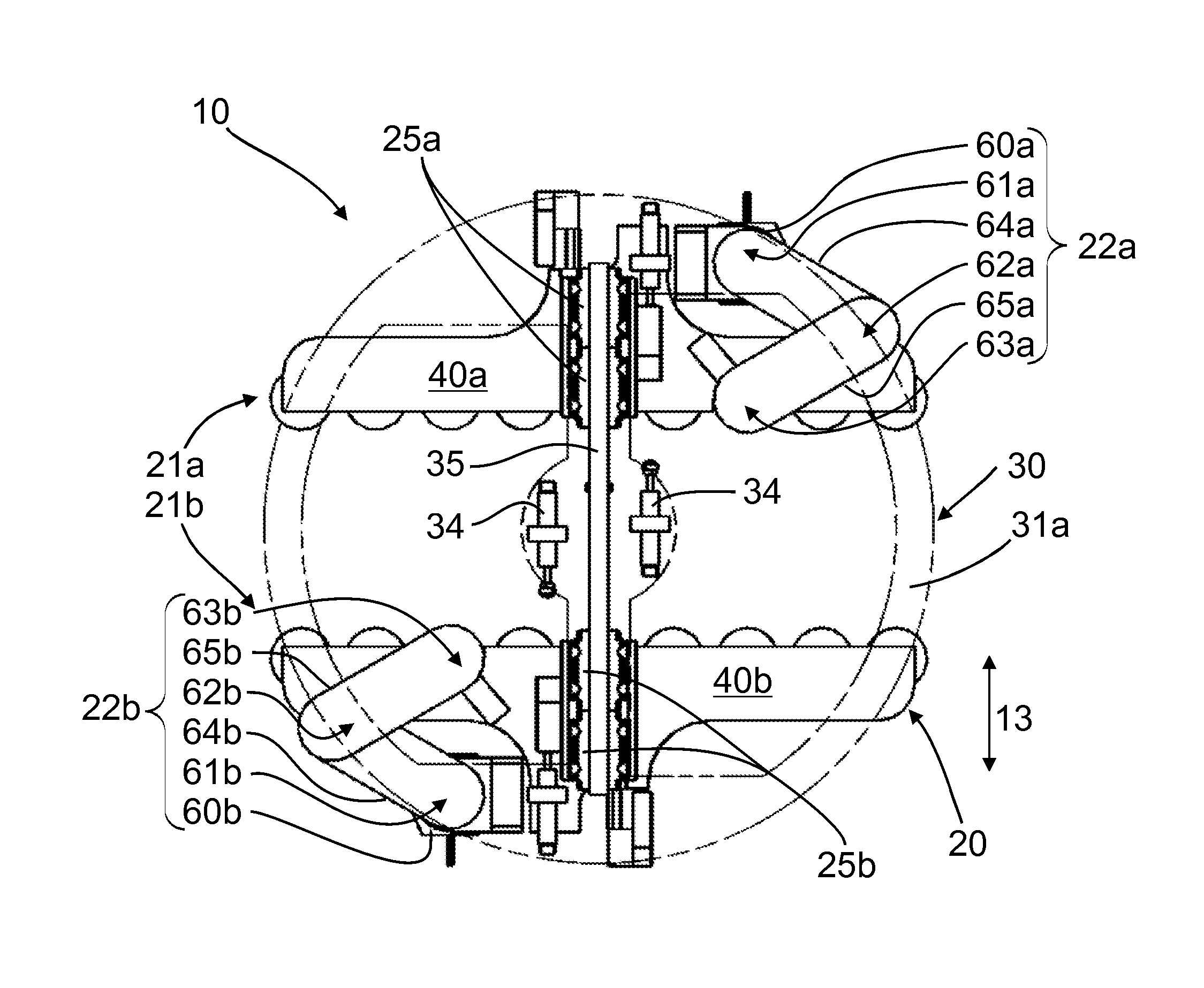
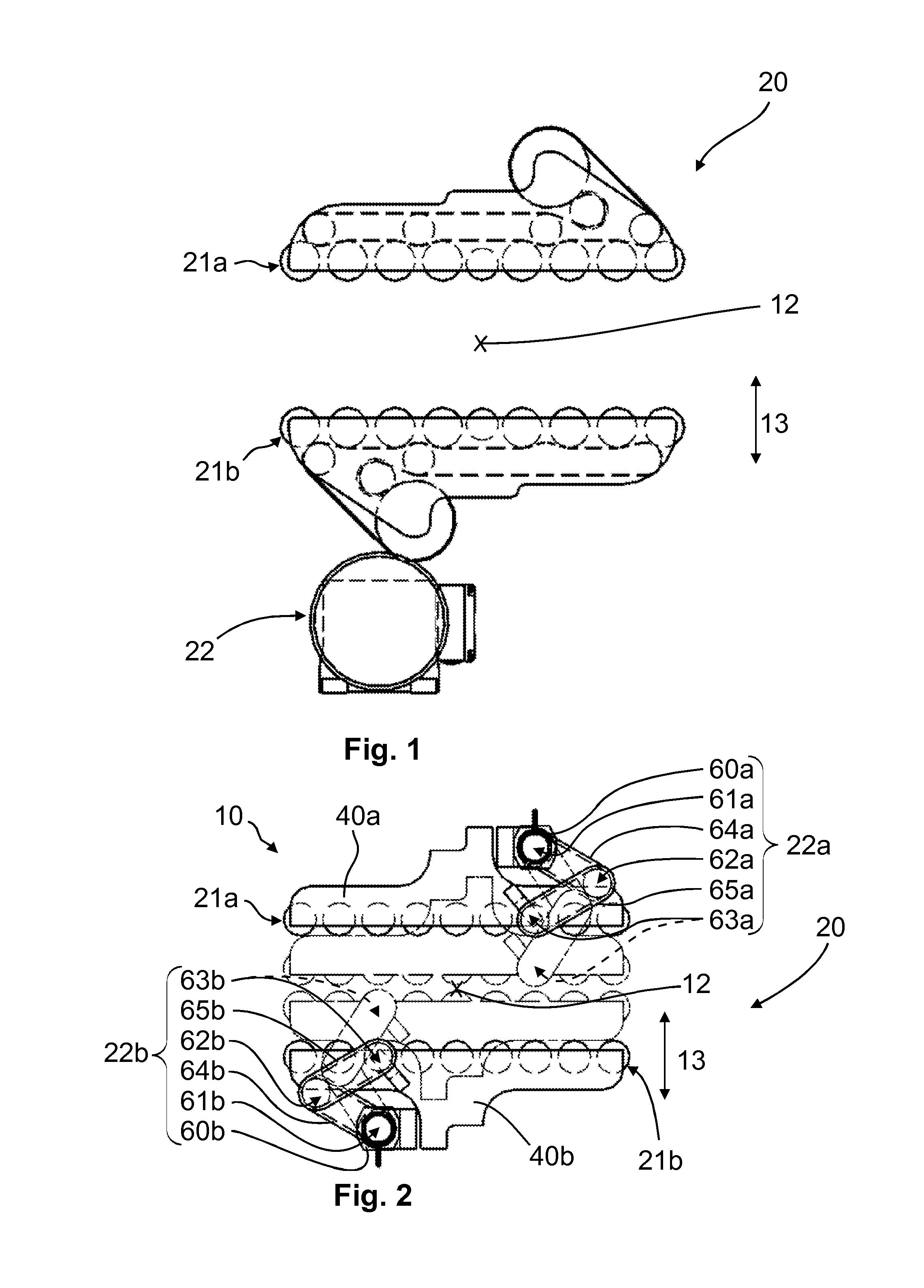
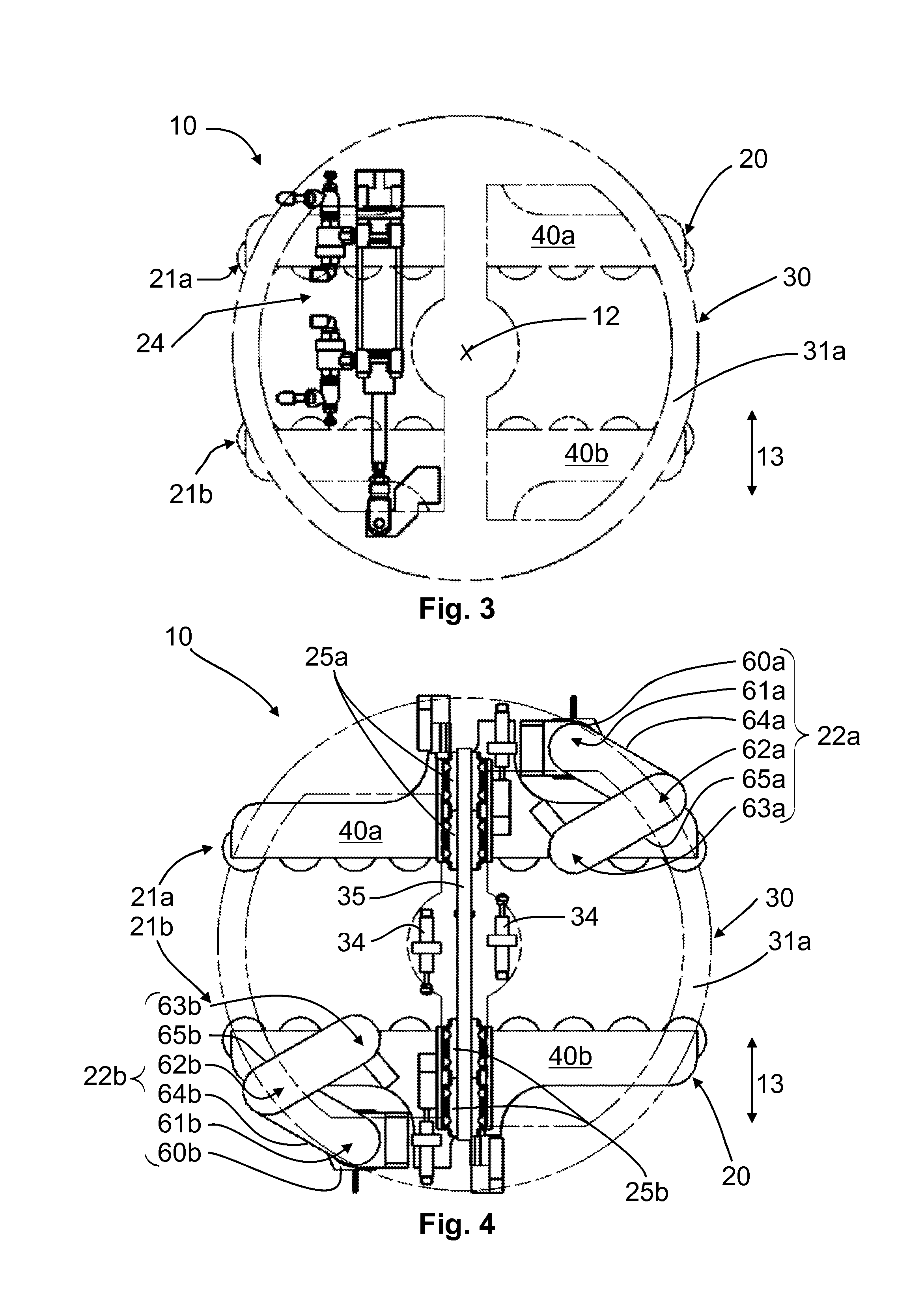
[0030]FIG. 1 shows a device for turning over an object, as is known in the prior art, and FIG. 2 shows the device 10 according to the invention, wherein details are given below of the devices and their differences. The conventional device, similarly to the device 10 according to the invention, has a holder device 20 for the purpose of receiving, turning over, and releasing an object, said holder device 20 having two height-adjustable 13 transport elements 21a, 21b for the purpose of conveying the object and one transport drive 22 for the purpose of driving the transport elements 21a, 21b, and has a rotary device 30 for the purpose of rotating the transport elements 21a, 21b about a stationary axis of rotation 12, which is described in greater detail in the context of FIGS. 7 and 8.

[0031]The invention relates to the novel transport drive 22, as shown in FIG. 2, wherein in contrast to the conventional transport device 22 in FIG. 1, said transport drive 22 can move with a frame 31 of t...


PUM

PropertyMeasurementUnit
energyaaaaaaaaaa
movementaaaaaaaaaa
transport speedaaaaaaaaaa

Abstract

A device for turning over an object, particularly a package of stacked sacks, having a holder device for receiving, turning over, and releasing the object, the holder device including two transport elements for conveying the object, and including at least one transport drive for the purpose of driving the transport elements, and having a rotary device for rotating the transport elements about a stationary axis of rotation, the rotary device including a rotatable frame to fasten the transport elements on both sides thereof, wherein the transport elements are fastened to the frame in a manner allowing movement, and wherein the transport drive is fastened in a torque-proof manner to the frame.

Description

TECHNICAL FIELD[0001]The invention relates to a device for turning over an object, particularly a package of stacked sacks.BACKGROUND[0002]Devices for turning over objects are used in the transport and palletting of packages of stacked sacks. In this case, it sometimes happens that the sacks are not lying flat on top of each other, and the packages therefore sink in the middle. This can particularly occur if the sacks have folded bottoms or valves on their ends. In order to nonetheless obtain the flattest possible surface of such packages during palletting, it is therefore sometimes necessary to turn over the packages.[0003]A device for turning over an object is known from DE 199 31 145 A1, designed with a holder device for the purpose of receiving, turning over, and releasing the object, and a rotary device for the purpose of turning over the holder device. The holder device in this case has two transport elements which can grip the object, wherein the transport elements can be tur...

Claims


Application Information

Patent Timeline
Patent Type & Authority Patents(United States)
IPC IPC(8): B41F1/00B65H31/20B41F1/52B65H29/00B65G47/252B65H29/20
CPCB65G47/252B41F1/52B65H29/00B65H29/20B65H31/20B65G2207/14B65H2301/33214B65H15/02
Inventor HAWIGHORST, THOMASTITZ, ALEXANDERDUWENDAG, RUDIGERTILLMANN, GUIDO
Owner WINDMOELLER & HOELSCHER GMBH
Learn More