Multiple port discharge manifold fluid end

a discharge manifold and fluid end technology, which is applied in the direction of positive displacement liquid engines, piston pumps, liquid fuel engines, etc., can solve the problems of premature valve failure, high pressure and repetitive impact loading of the valve body and valve seat, and the sealing surface of the valve is subject to exceptionally harsh conditions, so as to reduce the risk of slipping, shorten the life of the valve, and increase the wall thickness

Active Publication Date: 2016-03-15
ALTIS INVESTMENTS LLC
View PDF2 Cites 15 Cited by
  • Summary
  • Abstract
  • Description
  • Claims
  • Application Information

AI Technical Summary

Benefits of technology

[0018]The present invention addresses the problem of instability in top stem guided valves due to non-symmetrical flow around the discharge valve which shortens valve life. The present invention restores symmetrical flow around the discharge valve by utilizing a multiple port discharge manifold.
[0019]In a representative embodiment of the disclosure, a positive displacement pump fluid end comprises at least one discharge fluid chamber, and the discharge fluid chamber further comprises a plunger bore, a discharge valve seat, a discharge valve; a suction fluid chamber and at least two discharge manifold ports on opposite sides of said fluid chamber. Fluid is discharged through the discharge seat by the forward stroke of a plunger in said plunger bore, and the flow of said discharged fluid is diverted around said discharge valve in a substantially uniform flow pattern to exit said fluid end through said at least two discharge manifold ports. At least one embodiment discloses the discharge fluid chamber being offset from the suction fluid chamber to increase the wall thickness around the discharge manifold connection on the side of the fluid end.
[0020]A representative fluid end housing comprising a dual port discharge manifold in accordance with embodiments of the invention is illustrated in FIGS. 10, 11, 12A, 12B, 12C, 12D and 13. Said dual port manifold connects adjacent discharge fluid chambers to channel discharge flow from the fluid end to one or more connections on the side of the fluid end. FIG. 11 illustrates how the dual port manifold restores symmetrical flow around the valve to increase valve performance. Symmetrical flow eliminates the forces that cause valve cocking and miss-alignment that shortens valve life. All plungers in the fluid end are arranged in a common plane defined by the crankshaft and crossheads in the power end of the pump. Various embodiments of the disclosure show different connections from the discharge manifold on each side of the fluid end housing.
[0021]Because the fluid chamber around the suction valve, is basically cylindrical, there is no change of direction in fluid flow immediately above the suction valve; flow through the valve and seat remains symmetrical, thus there is very little cocking or miss-alignment of the suction valve. In the area well above the suction valve, the fluid changes direction to enter the plunger bore, however this area is of such distance from the suction valve that the change of direction in the fluid flow does not affect the flow through the suction valve.

Problems solved by technology

Such valves typically experience high pressures and repetitive impact loading of the valve body and valve seat.
These severe operating conditions have in the past often resulted in leakage and / or premature valve failure due to metal wear and fatigue.
Valve sealing surfaces are subject to exceptionally harsh conditions in exploring and drilling for oil and gas, as well as in their production.
During fracturing, cracks are created in the rock of an oil bearing formation by application of high hydraulic pressure.
Unfortunately, both sand and aluminum oxide slurries are very abrasive, typically causing rapid wear of many component parts in the positive displacement plunger pumps through which they flow.
Accelerated wear is particularly noticeable in plunger seals and in the suction (i.e., intake) and discharge valves of these pumps.
The swirling turbulence in the sand slurry used in typical fracturing work results in sever abrasion of the metal valve body and the elastomeric insert seal, which quickly damages the seal, resulting in seal failure.
Once the seal fails on the valve insert, the high pressure fluid on the downstream side of the valve escapes through the seal failure to the low pressure upstream side of the valve.
Travelling from the very high pressure to the very low pressure side of the valve results in extreme velocities of the sand slurry, which rapidly erodes the metal valve body and the guide legs in the slurry's path; many times destroying the entire valve leg.
However in severe pumping environments with high pump rates and high slurry concentrations the problem described in the previous paragraph still existed as evidenced by the four (4) erosion marks and destroyed guide legs. FIG. 5B is a picture a valve of the prior art damaged by seal failure and severe erosion behind the guide legs.
However top stem design valves are inherently unstable in the open position, particularly the discharge valve in the discharge fluid chamber.
As the valve continues its cyclic repeating opening and closing, the sliding forces cause rapid and accelerating wear on the top stem guide.
This wear is accelerated by side loads on valve body that result when fluid flowing past the valve body changes its direction of flow into the discharge manifold.
Such bushings require periodic checking and replacement, but these steps may be overlooked by pump mechanics until a valve fails prematurely.
When the open valve is badly misaligned and the valve guide is badly worn there are not aligning forces available to properly align the valve as it closes.
In this position, the cocked valve leaves an extrusion gap that results in shorten valve insert seal life.
The cocked valve also results in uneven loading of the metal valve body against the seating surface of the seat resulting in accelerated metal wear on the valve body and seat.

Method used


Image

  • Multiple port discharge manifold fluid end
  • Multiple port discharge manifold fluid end
  • Multiple port discharge manifold fluid end

Examples


first embodiment

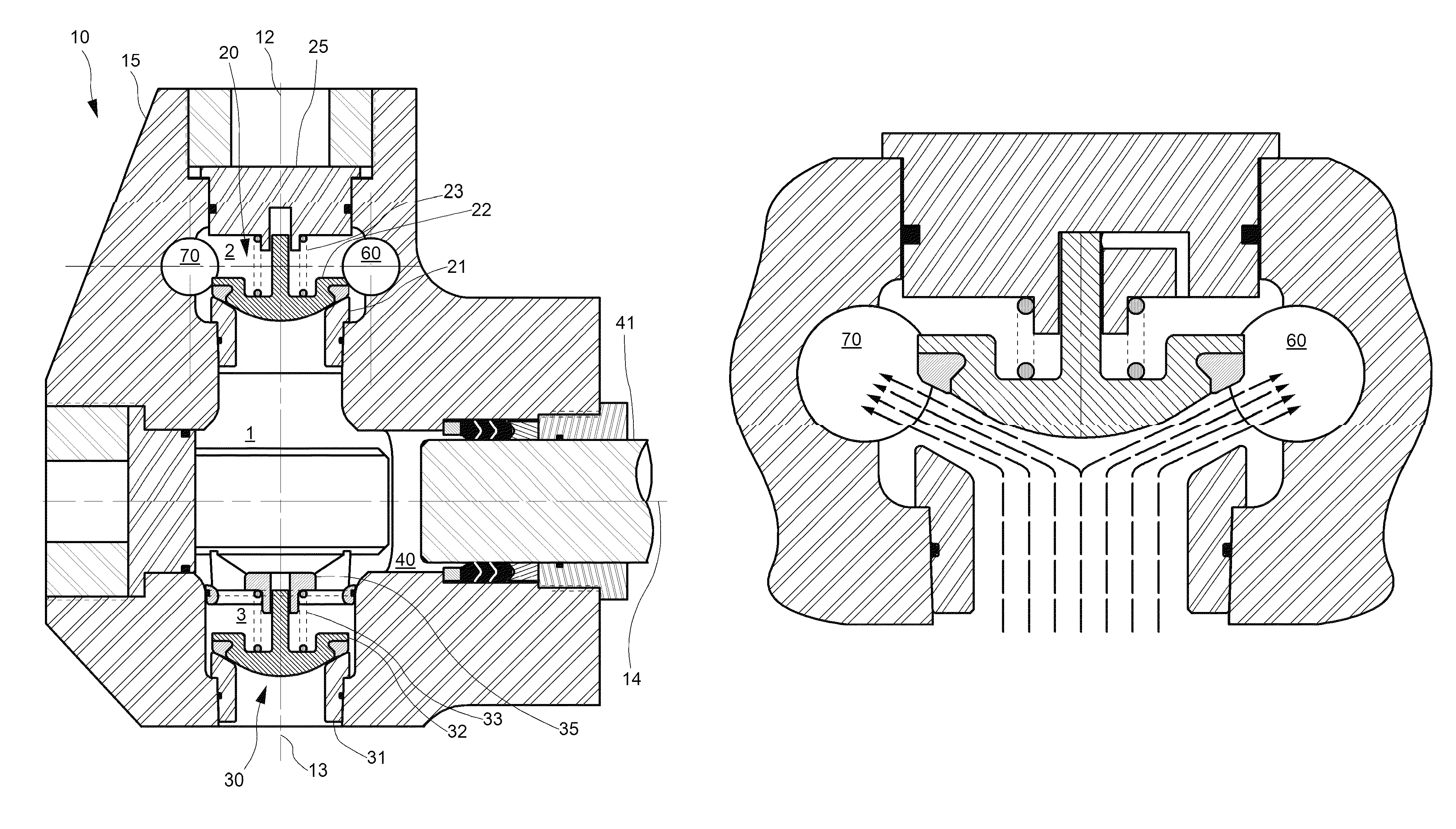
[0041]FIG. 10 schematically illustrates a cross-section of a right-angular plunger pump fluid end 10 of the present invention. Fluid end assembly composes a fluid end housing 15 with a central fluid chamber 1 which has a discharge fluid chamber 2 and a suction chamber 3, wherein discharge fluid chamber 2 contains a discharge valve and seat assembly 20. Said discharge valve and seat assembly includes discharge seat 21, discharge valve 22, discharge spring 23, and discharge cover guide 25. Similarly suction fluid chamber 3 contains a suction valve and seat assembly 30 composed of suction seat 31, suction valve 32, suction spring 33, and suction spring retainer guide 35. Discharge chamber 2 centerline 12 is collinear with suction chamber centerline 13 in the Central fluid chamber 1 also contains a plunger bore 40 and associated plunger 41; plunger bore 40 and plunger 41 are concentric to plunger centerline 14.

[0042]Additionally FIG. 10 illustrates discharge fluid chamber 2 which is co...

second embodiment

[0046]FIG. 12C schematically illustrates top sectional view this invention in which fluid end block 16 is fitted with a distal port 80 and a proximal port 90. Each port being through bored into fluid end block 16. Distal port 80 has dual connections 81 and 82 on opposite sides 18 and 19 of fluid end housing to connect the discharge flow to external piping. Similarly proximal port 90 has dual connections 91 and 92 on opposite sides 18 and 19 of fluid end housing to connect the discharge flow to external piping.

third embodiment

[0047]FIG. 12D schematically illustrates top sectional view of third embodiment of this invention in which fluid end block 17 is fitted with a distal port 60 and a proximal port 50. Each port being blind bored from the same side of fluid end block 17; either side 18 or 19. Illustrated in this figure, distal port 60 and proximal port 50 each have a connection 61 and 51 respectfully on side 18 of the fluid end housing 17 at the exit of the respective ports 60 and 50 to connect the discharge flow to external piping.


PUM


Abstract

A fluid end assembly comprising a fluid end housing with multiple discharge manifold ports which provide a fluid end assembly that overcomes problems associated with prior art single port discharge manifold designs that result in non-symmetrical flow of discharged fluids through the fluid end discharge valves, resulting in premature failure of said valves. The multiple port discharge manifolds overcome problems associated with non-symmetrical flow of discharged fluids through a fluid end discharge valve, thereby improving valve life and performance.

Description

PRIORITY DATA[0001]This patent application claims priority to U.S. Provisional Patent Application Ser. No. 61 / 656,718 filed on Jun. 7, 2012. By this reference, the aforementioned provisional patent application is incorporated herein for all purposes.FIELD OF THE INVENTION[0002]The invention generally concerns high-pressure plunger-type pumps useful, for example, in oil well hydraulic fracturing. More specifically, the invention relates to fluid end discharge manifolds suitable pumping abrasive fluids, such as sand slurries at high pressures.BACKGROUND OF THE INVENTION[0003]Engineers typically design high-pressure oil field plunger pumps in two sections; the (proximal) power section and the (distal) fluid section. The power section usually comprises a crankshaft, reduction gears, bearings, connecting rods, crossheads, crosshead extension rods, etc. The power section is commonly referred to as the power end by the users and hereafter in this application. The fluid section is commonly ...

Claims


Application Information

Patent Timeline
Patent Type & Authority Patents(United States)
IPC IPC(8): F04B7/02F04B15/02F04B23/06F04B7/00F04B53/10F04B53/16
CPCF04B7/0023F04B15/02F04B23/06F04B53/10F04B53/16
Inventor BLUME, GEORGE, H
Owner ALTIS INVESTMENTS LLC
Why Eureka
Try Eureka