Vessel comprising a crane

a technology of a crane and a swivel is applied in the field of a swivel, which can solve the problems of swivel member not being able to move back to its inward position, and the mechanism could jam

Active Publication Date: 2016-03-22
IHC HOLLAND NV
View PDF7 Cites 5 Cited by
  • Summary
  • Abstract
  • Description
  • Claims
  • Application Information

AI Technical Summary

Benefits of technology

[0017]As a result, the rotation mechanism is not fixedly attached to the vessel or the base member, but is connected to the vessel via the swivel member. The swivel member allows the rotation mechanism to move in a direction away from the vessel when moving from the upper position to the lower position and vice versa. This provides the end of the rotation mechanism attached to the frame with an increased freedom of movement, thereby allowing the crane to reach a relatively low position.
[0018]Such a crane is capable of positioning the top of the crane in a relatively low position with respect to a base of the crane. As a result, the distance from the top of the crane to the water surface is reduced and the length of the free end of the hoisting cable is thus also reduced. By reducing the free end of the hoisting cable, the natural frequency of the hoisting cable is no longer close to the frequency of the waves thereby reducing the chance of excessive swing.
[0019]Such a crane further provides the advantage that the top of the crane can be positioned in a relatively low position with respect to the base of the crane, while the footprint of the crane (i.e. the area on the deck occupied by the base), is relatively small.
[0020]By connecting the rotation mechanism to the vessel via the swivel member, the rotation mechanism is provided with an increased freedom of movement.
[0024]a spacer arranged between the frame and one of the swivel member, the rotation mechanism and the connection between the swivel member and the rotation mechanism, preventing the longitudinal body axis of the rotation mechanism and the longitudinal body axis of the swivel member from reaching a parallel position.

Problems solved by technology

In case the rotation mechanism and the swivel member would reach a parallel position, the mechanism could jam, i.e. the swivel member would not be able to move back to its inward position when the rotation mechanism moves the frame towards the upper position.

Method used


Image

  • Vessel comprising a crane
  • Vessel comprising a crane
  • Vessel comprising a crane

Examples


Embodiment Construction

[0035]Embodiments will now be described by way of example with reference to the Figures.

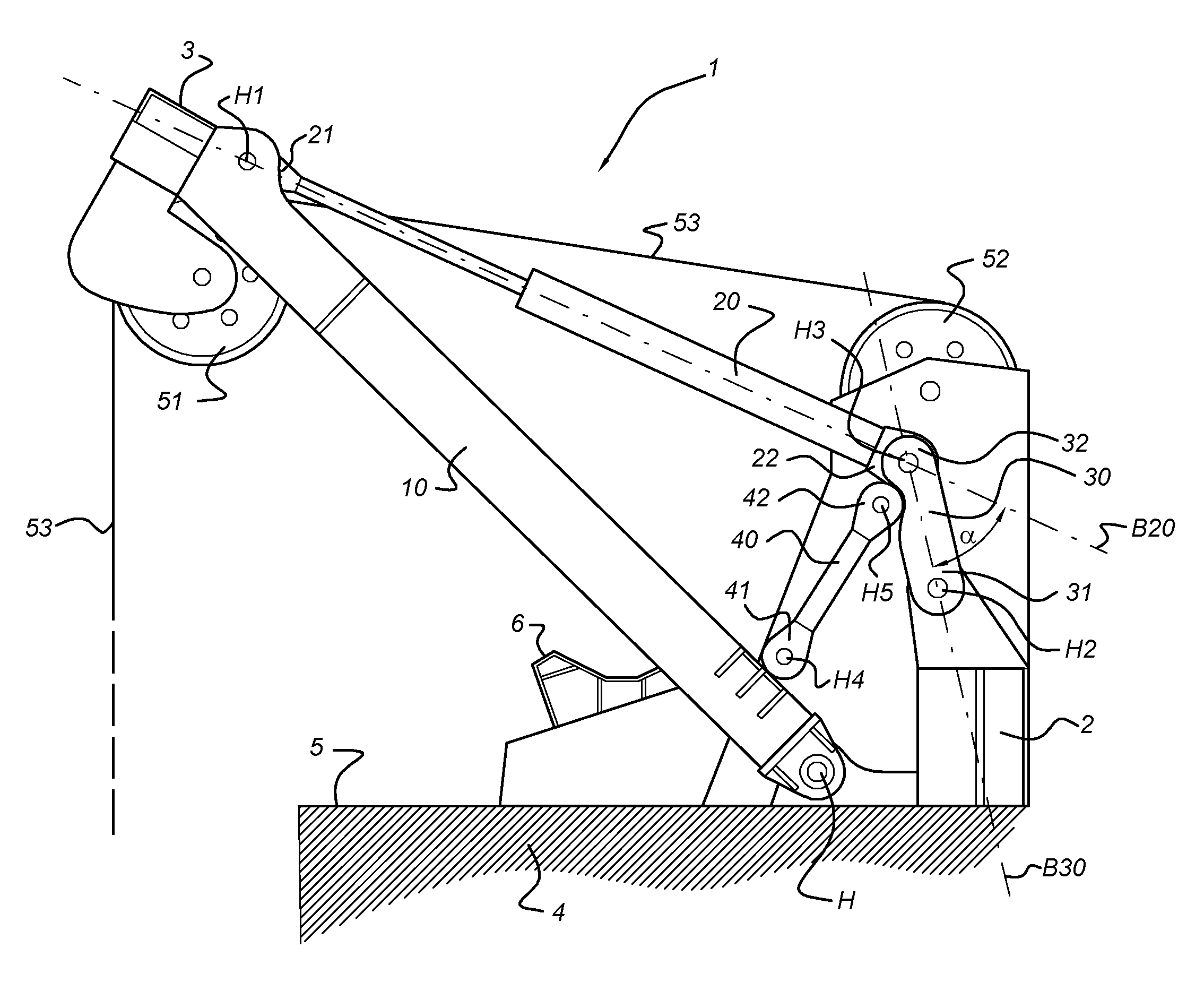
[0036]FIG. 1 schematically depicts a crane 1 mounted on a deck 5 of a vessel 4 (only partially shown).

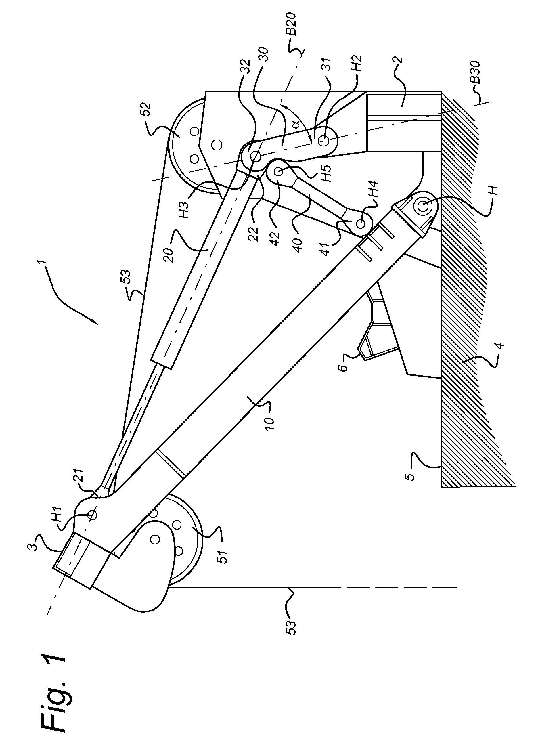
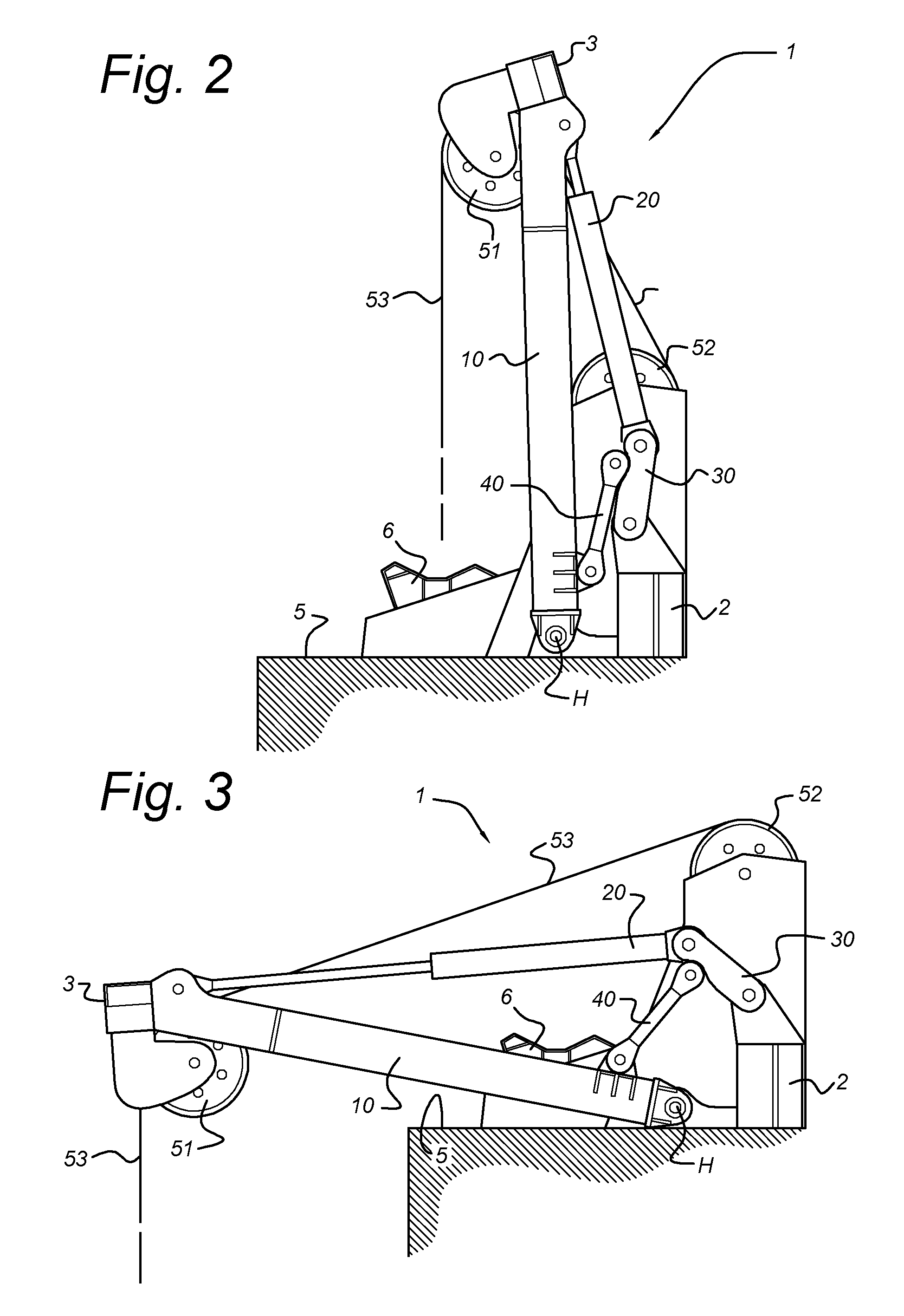
[0037]The crane 1 comprises a frame 10 which can be rotated about a horizontal hinge axis H. The crane 1 can be moved between an upper position (FIG. 2) and a lower position (FIG. 3). FIG. 1 shows the crane 1 in an intermediate position in between the upper position and the lower position.

[0038]By moving the crane 1 from the upper to the lower position (or vice versa), a load (not shown) can be moved from an onboard position to an overboard position (or vice versa).

[0039]On the deck 5 a receptacle 6 may be mounted directly under the top 3 of the crane 1 in the upper position. The receptacle 6 may be arranged to receive the load which is to be hoisted by the crane 1 from the receptacle 6 (onboard position) to an overboard position. The load may for instance be dredging equipment, such as a suction...


PUM


Abstract

A vessel (4) includes a crane (1) connected to a deck (5) of the vessel. The crane (1) includesa frame (10) which is rotatable about a horizontal hinge axis (H),a rotation mechanism (20) connected to the frame (10) at a position away from the horizontal hinge axis (H), arranged to rotate the frame (10) about the horizontal hinge axis (H) from an upper position to a lower position and vice versa, anda swivel member (30), which is with a first end (31) rotatable connected to the deck (5) and which is with a second end (32) rotatable connected to the rotation mechanism (20). The swivel member (30) is rotatable between an inward position associated with the upper position of the frame (10) to an outward position associated with the lower position of the frame (10).

Description

TECHNICAL FIELD[0001]The invention relates to a vessel comprising a crane, the crane being connected to a deck of the vessel, the crane comprising[0002]a frame which is rotatable about a horizontal hinge axis, and[0003]a rotation mechanism connected to the frame at a position away from the horizontal hinge axis, which is arranged to rotate the frame about the horizontal hinge axis from an upper position to a lower position and vice versa, wherein in the upper position a top of the crane is higher than in the lower position.STATE OF THE ART[0004]Cranes on vessels are used to load or unload loads from or to the vessel. The cranes may also be used to hoist equipment from the vessel into the sea or from the sea onto the vessel. The equipment may for instance be dredging equipment, such as a suction pipe or excavation tool.[0005]NL1004451C1 describes such a crane comprising a frame which is positioned on a deck of a vessel and is connected to the vessel by means of a hinge axis. The cran...

Claims


Application Information

Patent Timeline
Patent Type & Authority Patents(United States)
IPC IPC(8): B66C23/53B63B27/10B66C23/82B66C23/52E02F3/46E02F3/88E02F3/90
CPCB63B27/10B66C23/52B66C23/82E02F3/46E02F3/8841E02F3/905
Inventor KWELDAM, DENNISBIJVOET, ERWIN CORNELIS JOHANNES
Owner IHC HOLLAND NV
Why Eureka
Try Eureka