Rapid test device

a test device and liquid sample technology, applied in the field of liquid sample testing technique, can solve the problems of weak leakage prevention effect and affect the accuracy of test, and achieve the effect of improving the leakage prevention effect and improving the accuracy of test results

Active Publication Date: 2016-03-22
ASSURE TECH HANGZHOU
View PDF7 Cites 2 Cited by
  • Summary
  • Abstract
  • Description
  • Claims
  • Application Information

AI Technical Summary

Benefits of technology

[0007]In this connection, the present invention provides a rapid test device ensuring the same extracted volume of liquid sample each time, which improves the accuracy of test results.
[0017]From the above technical solutions it should be noted, the present invention connects the first chamber with the dosing piston assembling hole communicating with the second chamber; the dosing piston, inserted in the dosing piston assembling hole and provided with a dosing slot thereon. The dosing piston can be rotated by using the key. The liquid sample flows from the first chamber into the dosing slot. By rotating the key, the liquid sample in the dosing slot can be transmitted into the second chamber, wherein the liquid sample flows by the test paper. A part of liquid sample is absorbed by the test paper in the partition, and test result appears on the test paper. Since the dosing slot is machined on the dosing piston, the volume of the liquid sample obtained each time is equal and the accuracy of test result is improved. The dosing piston used to obtain the liquid sample is changed from being pushed linearly to being moved rotationally, which makes leak-proof effect better.

Problems solved by technology

However, the movable element of the test device of the art is piston and the silicone seal ring is used, which makes the leak-proof effect weaker.
The extracted volume of liquid sample each time is different, thereby affecting the accuracy of test results.

Method used


Image

  • Rapid test device
  • Rapid test device
  • Rapid test device

Examples


Embodiment Construction

[0023]The invention discloses a rapid test device, wherein the volume of the liquid sample obtained each time is equal and the accuracy of test result is improved.

[0024]The technical solutions in embodiments of the present invention are described clearly and completely as below with help of figures in embodiments of the present invention.

[0025]Apparently, the described embodiments are only a part of the embodiments of the present invention, but not all embodiments. Based on the embodiments of the present invention, all other embodiments obtained by those ordinary skilled in the art without giving creative efforts, belonging to the protection scope of the present invention.

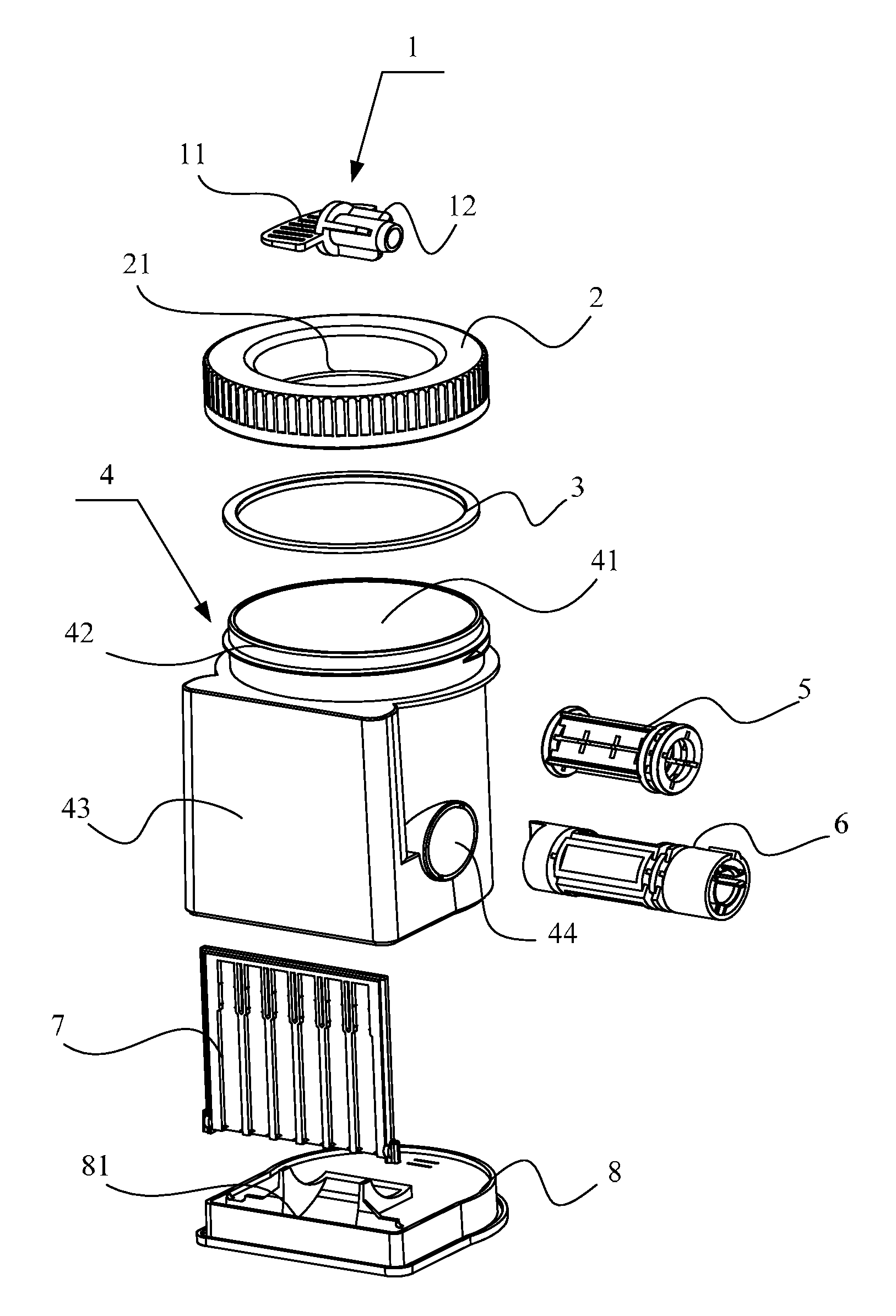
[0026]Please refer to FIG. 1-FIG. 4.

[0027]FIG. 1 is breakdown schematic for embodiments of the rapid test device

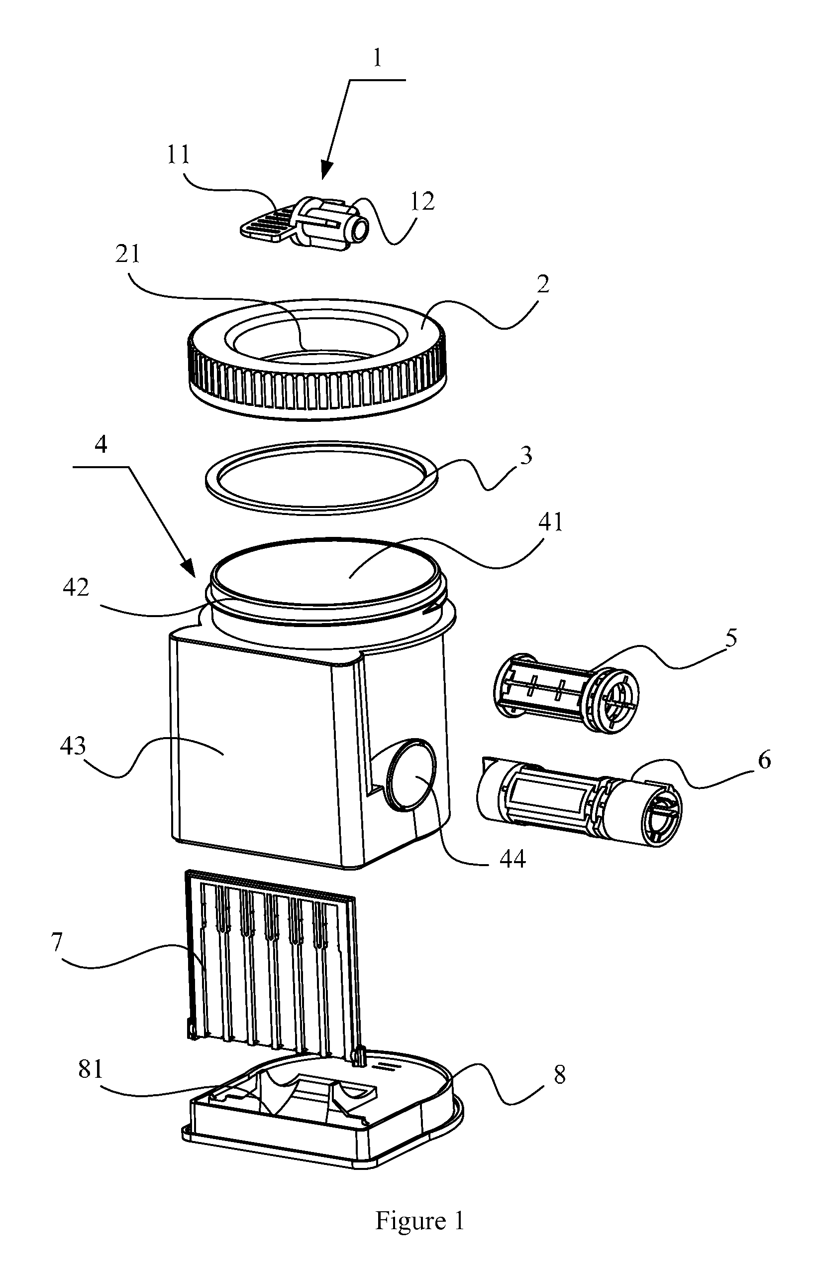
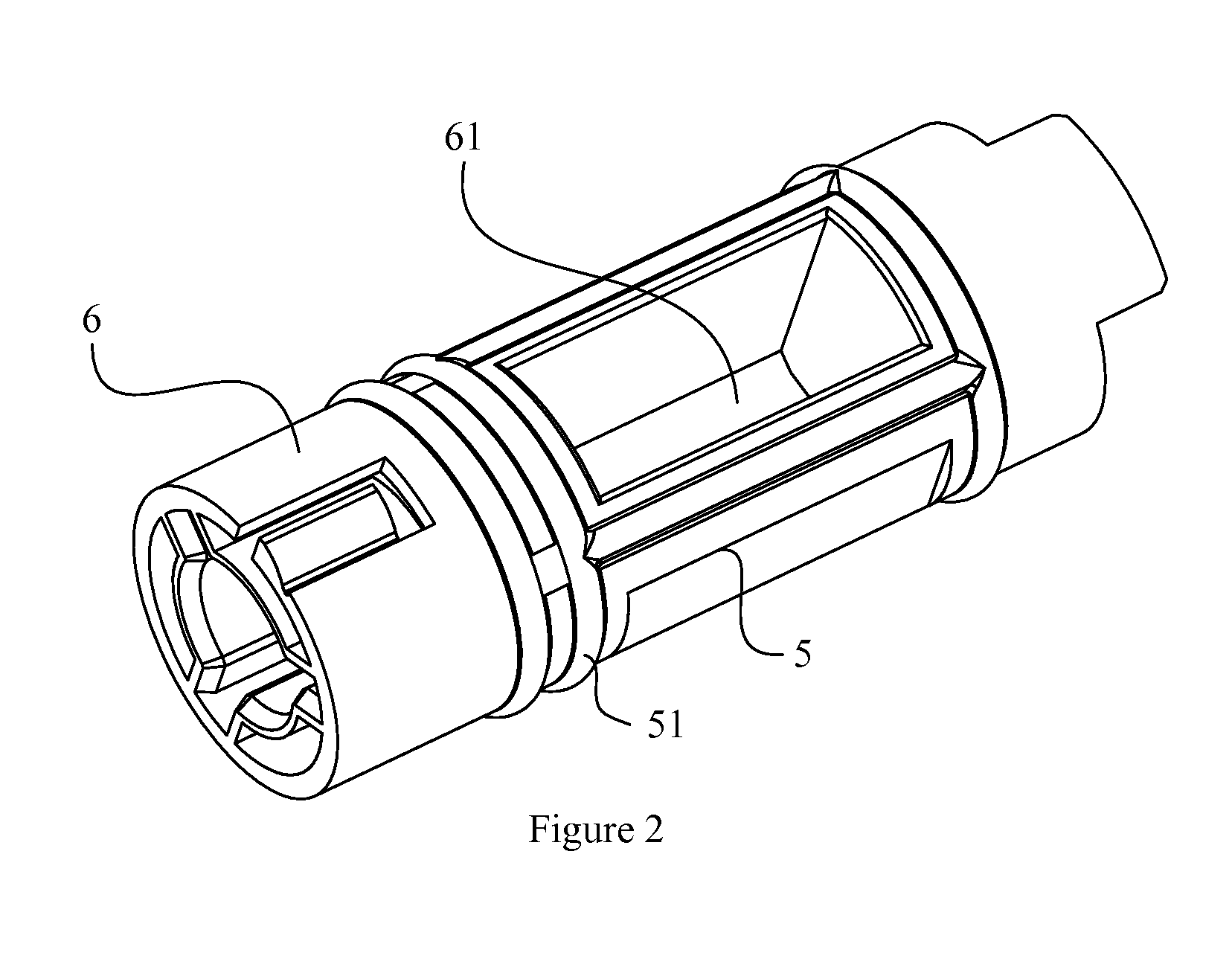
[0028]FIG. 2 is structure schematic for dosing piston in embodiments of the present invention

[0029]FIG. 3 is side cutaway view in embodiments of the rapid test device

[0030]FIG. 4 is rear cutaway view in e...


PUM

PropertyMeasurementUnit
transparentaaaaaaaaaa
shore hardnessaaaaaaaaaa
liquid sample testingaaaaaaaaaa

Abstract

The invention discloses a rapid test device, includes a cup vessel (4), which comprises a first chamber (41) and a dosing piston assembling hole (44) communicating with the first chamber (41); a base (8) fastened at the bottom of the cup vessel (4); a second chamber (81), formed between the base (8) and the cup vessel (4) and communicating with the dosing piston assembling hole (44); a partition (7), arranged in the second chamber (81) and provided with test paper; a dosing piston (6), provided with a dosing slot (61) thereon and provided with a key hole at one end, inserted in the dosing piston assembling hole (44); and a key (1) matching the key hole. In present invention the sample in the dosing slot can be transmitted into the second chamber by rotating the dosing piston. The sample is absorbed by the test paper after flowing by the test paper, and test result appears on the test paper. Since the dosing slot is machined on the dosing piston, the volume of the liquid sample obtained each time is equal and the accuracy of test result is improved. The dosing piston used to obtain the liquid sample is changed from being pushed linearly to being moved rotationally, which makes leak-proof effect better.

Description

CROSS REFERENCE TO RELATED PATENT APPLICATION[0001]The present application is the US national stage of PCT / CN2011 / 073169 filed on Apr. 22, 2011 which claims the priority of the Chinese patent application No. 201110025024.9 filed on Jan. 24, 2011, which application is incorporated herein by reference.FIELD OF THE INVENTION[0002]The present invention relates to liquid sample testing technique, and particularly relates to a rapid test device.BACKGROUND OF THE INVENTION[0003]The rapid test device can detect the substances contained in the sample quickly and effectively and provide those skilled in the art a basis for qualitative judgment.[0004]There're already many rapid test devices, wherein the most commonly used is test device detecting liquid sample, which prevents those skilled in the art from touching the sample and makes operation simple, and ensures the accuracy of test result.[0005]Such as an announcement of the Chinese patent No. CN1834622A discloses a test device and testing ...

Claims


Application Information

Patent Timeline
Patent Type & Authority Patents(United States)
IPC IPC(8): G01N1/10B01L3/00G01L7/18G01N35/00
CPCG01L7/18B01L3/502B01L2200/0605B01L2200/0689B01L2300/042B01L2300/046B01L2300/0663B01L2400/0457B01L2400/0644G01N2035/00108
Inventor LING, SHISHENGJI, XUEHAOYAO, KEYUAN
Owner ASSURE TECH HANGZHOU
Why Eureka
Try Eureka