Electrophoretic display design

a display design and display technology, applied in the field of electrophoretic display designs, can solve the problems of visual display defect, two microcups will become connected,

Active Publication Date: 2016-03-22
E INK CALIFORNIA
View PDF13 Cites 25 Cited by
  • Summary
  • Abstract
  • Description
  • Claims
  • Application Information

AI Technical Summary

Benefits of technology

[0017]c) the second shape is 90% or less of the first shape in area.

Problems solved by technology

For this type of design, one disadvantage is that if the partition wall between the two neighboring microcups has a defect, the two microcups will become connected.
Due to the pumping action of operating the display, one microcup will turn white and one black, producing a visual display defect.

Method used


Image

  • Electrophoretic display design
  • Electrophoretic display design
  • Electrophoretic display design

Examples


Embodiment Construction

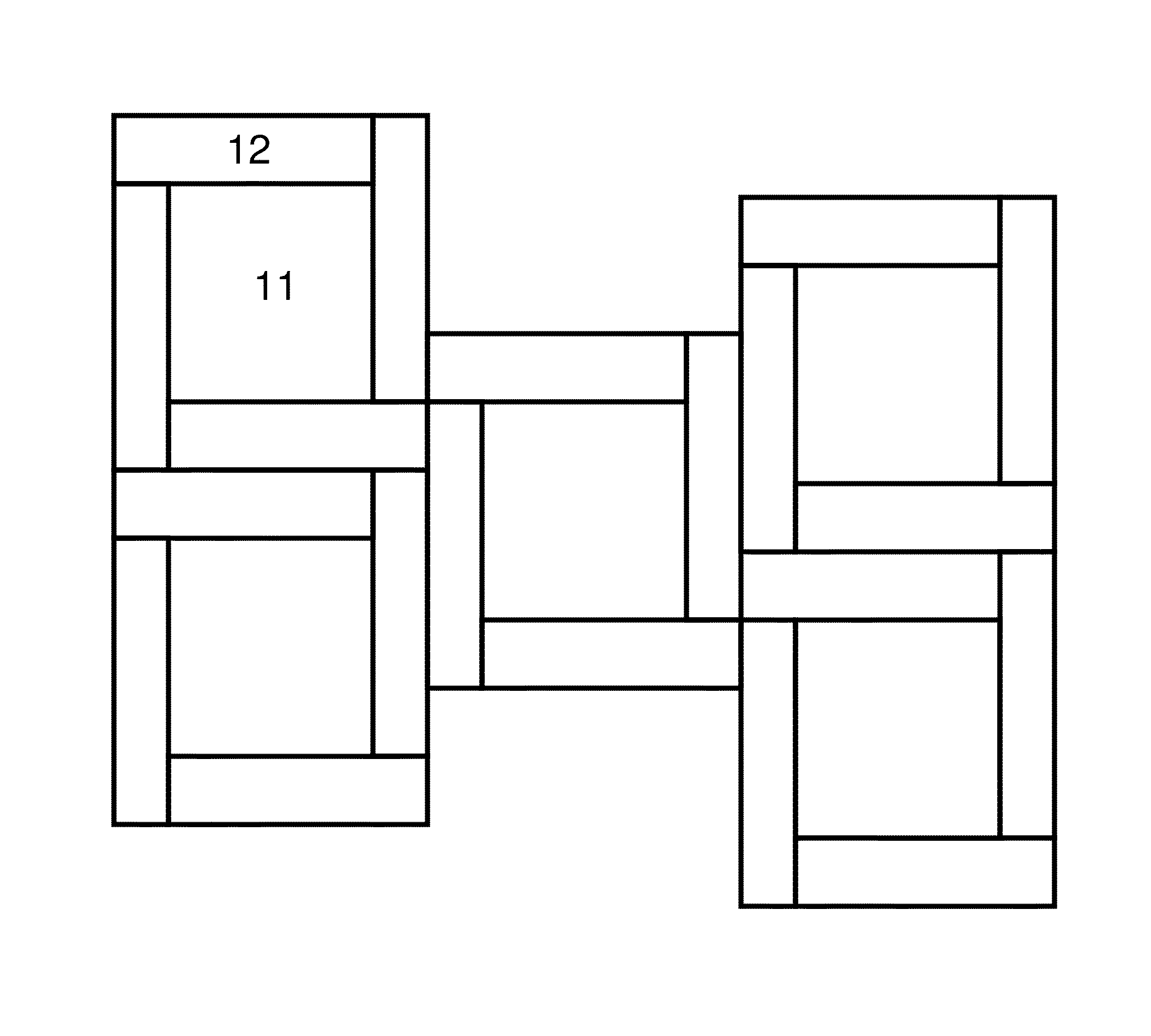
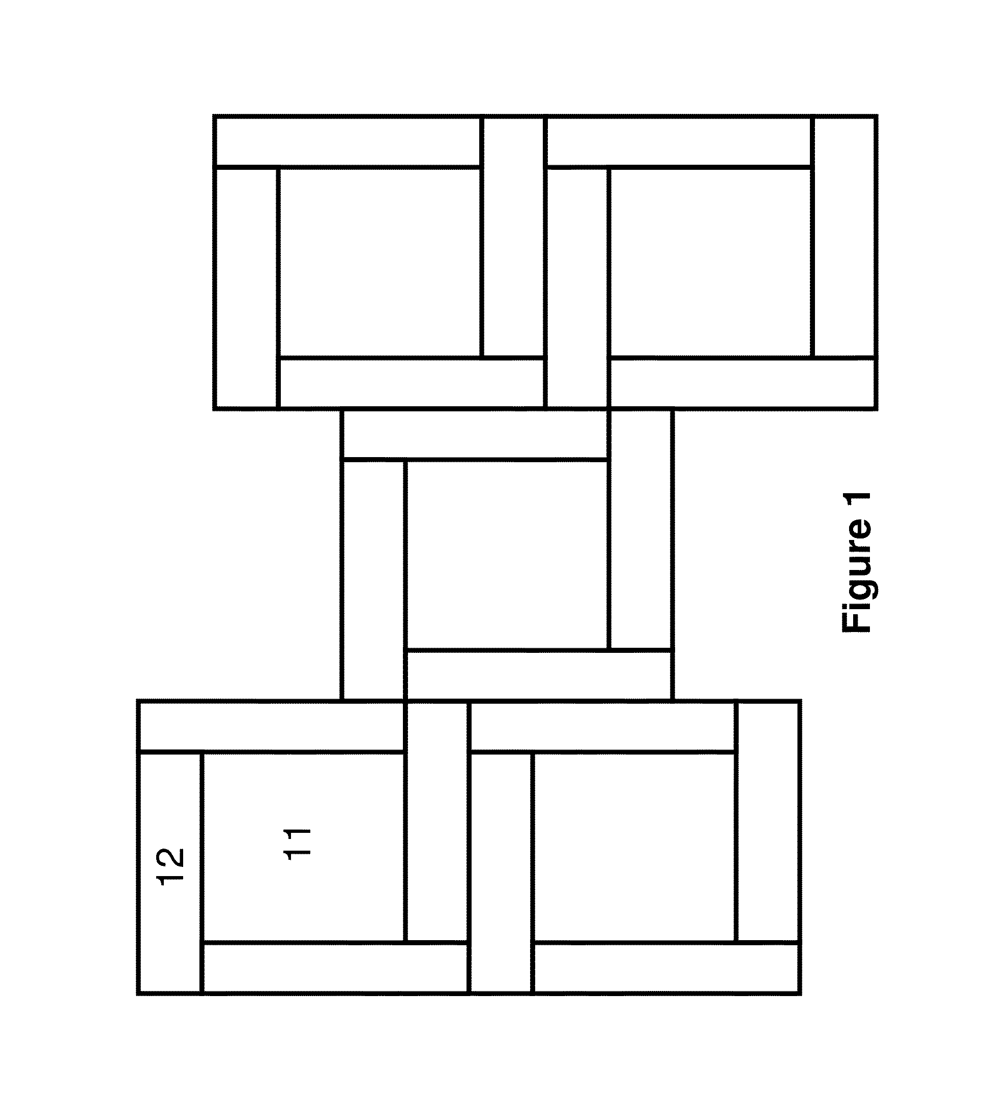
[0021]The first aspect of the present invention is directed to a design of the microcup arrangement.

[0022]In this design, the microcups are divided into two groups. The first group has a first shape and the second group has a second shape. In the context of this aspect of the present invention, the term “shape” refers to the two-dimensional shape of the top opening of a microcup, on the viewing side.

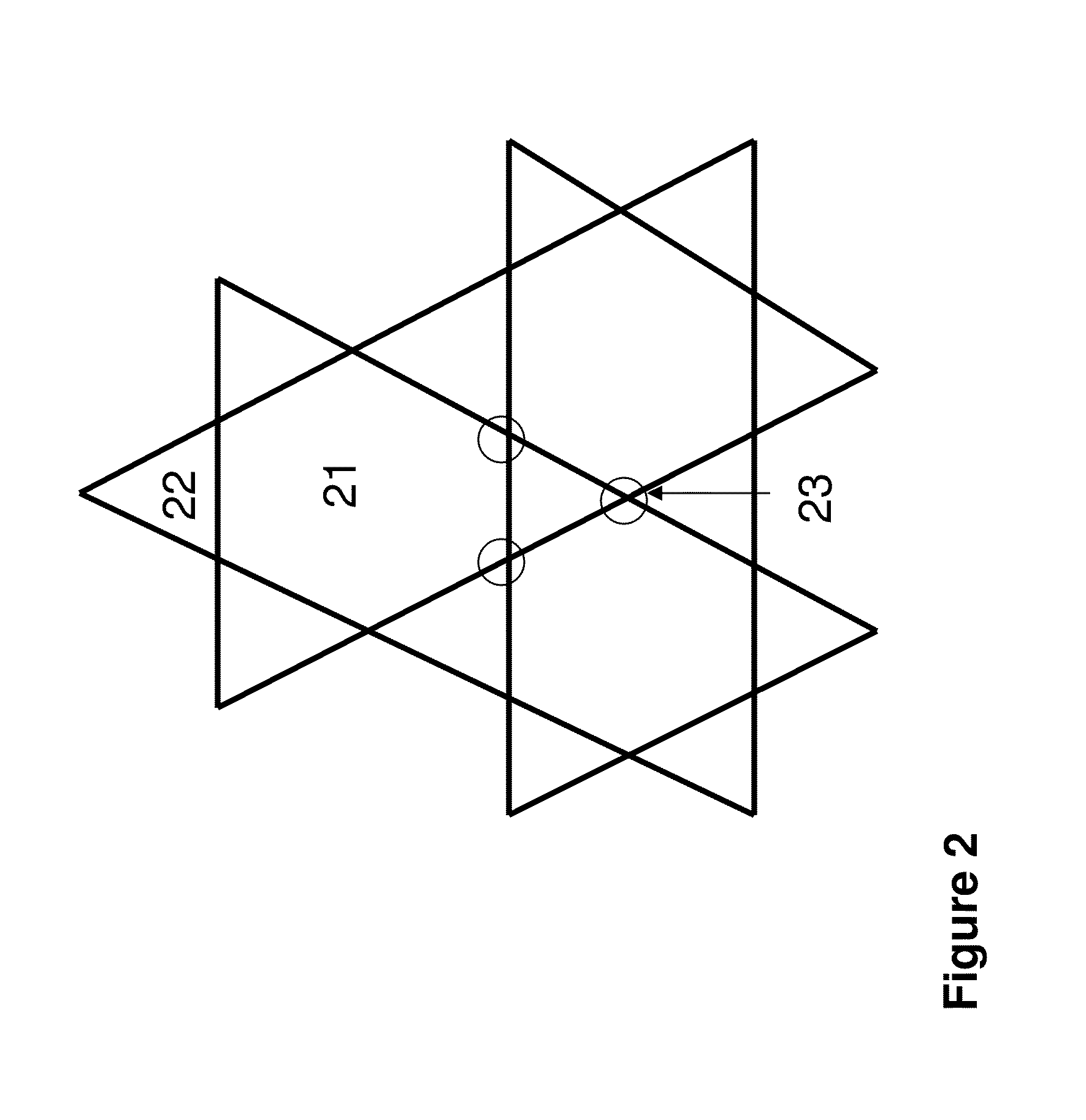
[0023]One microcup of the first shape is surrounded by the microcups of the second shape. Therefore, either there is no contact at all between any two microcups of the first shape or two microcups of the first shape may have only contact points.

[0024]FIG. 1 depicts an example in which a microcup of a first shape (square) (11) is surrounded by the microcups of a second shape (rectangular) (12). As shown, in this case, there is no contact between any two microcups of the first shape (11).

[0025]FIG. 2 is another example in which a microcup of a first shape (hexagonal) (21) is surrounded by ...


PUM

PropertyMeasurementUnit
widthaaaaaaaaaa
widthaaaaaaaaaa
shapeaaaaaaaaaa

Abstract

The present invention is directed to electrophoretic displays comprising microcups of a first shape and the microcups of a second shape, wherein each of the microcups of the first shape is surrounded by the microcups of the second shape, and the second shape is 90% or less of the first shape in area. The present electrophoretic displays comprise novel microcup designs, which may reduce the appearance of defects in the display images.

Description

[0001]This application claims priority to U.S. Provisional Application No. 61 / 596,075, filed Feb. 7, 2012; which is incorporated herein by reference in its entirety.FIELD OF THE INVENTION[0002]The present invention is directed to electrophoretic display designs, aiming to reduce noticeable defects of display images, without changing the fill factor of the display cells.BACKGROUND OF THE INVENTION[0003]U.S. Pat. No. 6,930,818 discloses an electrophoretic display based on the microcup technology. The patent describes the manufacture of microcups as display cells, by microembossing or imagewise exposure. The microcups are then filled with an electrophoretic fluid comprising charged pigment particles dispersed in a solvent or solvent mixture.[0004]The top openings of the microcups traditionally may have the same size and shape and such microcups spread across the entire display surface. For example, all of the microcups may have a top opening of a square shape on the viewing side or all...

Claims


Application Information

Patent Timeline
Patent Type & Authority Patents(United States)
IPC IPC(8): G02F1/167G02F1/1333G02B1/06
CPCG02F1/167G02F1/133377G02B1/06G02F2001/1672G02F1/1681
Inventor LIN, CRAIGSPRAGUE, ROBERT A.
Owner E INK CALIFORNIA
Why Eureka
Try Eureka