
Signal amplification apparatus and method

a signal amplification and signal technology, applied in the field of signal amplification apparatus and method, can solve the problems of polar transmitter structure, low efficiency of polar transmitter, and low efficiency of envelope modulator for providing envelope signal to power amplifier, so as to achieve low nonlinearity and high efficiency

Active Publication Date: 2016-03-22
ELECTRONICS & TELECOMM RES INST
View PDF19 Cites 0 Cited by
  • Summary
  • Abstract
  • Description
  • Claims
  • Application Information

AI Technical Summary

Benefits of technology

[0007]In view of the above, the present invention provides a signal amplification apparatus and method having a structure that is less vulnerable to nonlinearity and maintains high efficiency despite an envelope voltage being lowered.
[0013]Further, the noise remover may set output matching to be in a narrow band to remove quantization noise from the amplified signal output by the power amplifier.
[0019]Further, the noise remover may set output matching to be in a narrow band to remove quantization noise from the amplified signal output by the power amplifier.
[0023]Further, the signal amplification method may further comprise removing quantization noise from the amplified output signal.
[0026]Further, the signal amplification method may further comprise removing quantization noise from the amplified output signal.

Problems solved by technology

However, an OFDM based transmitter has a limitation in that its power amplifier does not work efficiently due to overcome the limitation, a variety of transmission structures are proposed, one of which is a polar transmitter structure for separately transmitting a phase signal and an envelope signal to a power amplifier.
Such low envelop voltage causes several limitations.
First, efficiency in an envelope modulator for providing the envelope signal to the power amplifier is rapidly reduced when a level of the envelope signal is smaller than a specific level.
Accordingly, the polar transmitter structure operates less efficiently in a period where an envelope level is small.
Furthermore, if the envelope voltage decreases to a knee voltage of the power amplifier or lower, nonlinearity of the power amplifier may increase rapidly to reduce signal quality.

Method used


Image

  • Signal amplification apparatus and method
  • Signal amplification apparatus and method
  • Signal amplification apparatus and method

Examples


Embodiment Construction

[0034]Advantages and features of the invention and methods of accomplishing the same may be understood more readily by reference to the following detailed description of embodiments and the accompanying drawings. The invention may, however, be embodied in many different forms and should not be construed as being limited to the embodiments set forth herein. Rather, these embodiments are provided so that this disclosure will be thorough and complete and will fully convey the concept of the invention to those skilled in the art, and the invention will only be defined by the appended claims. Like reference numerals refer to like elements throughout the specification.

[0035]In the following description of the present invention, if the detailed description of the already known structure and operation may confuse the subject matter of the present invention, the detailed description thereof will be omitted. The following terms are terminologies defined by considering functions in the embodim...


PUM


Abstract

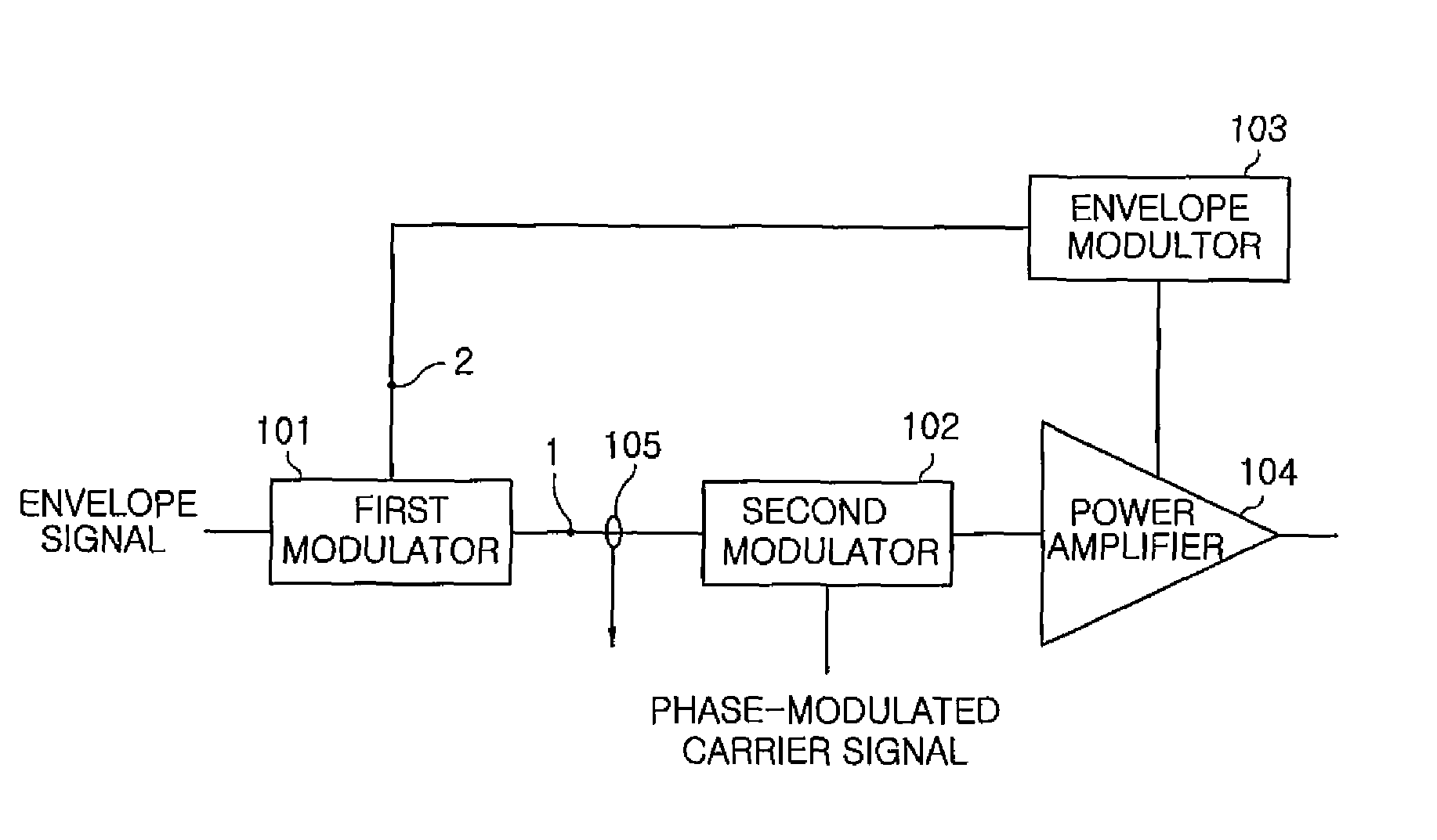
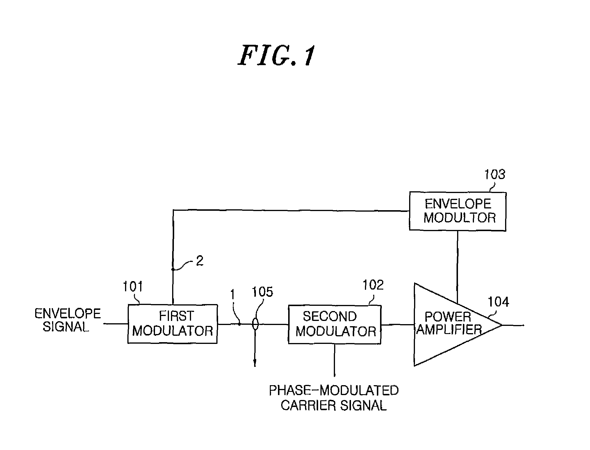
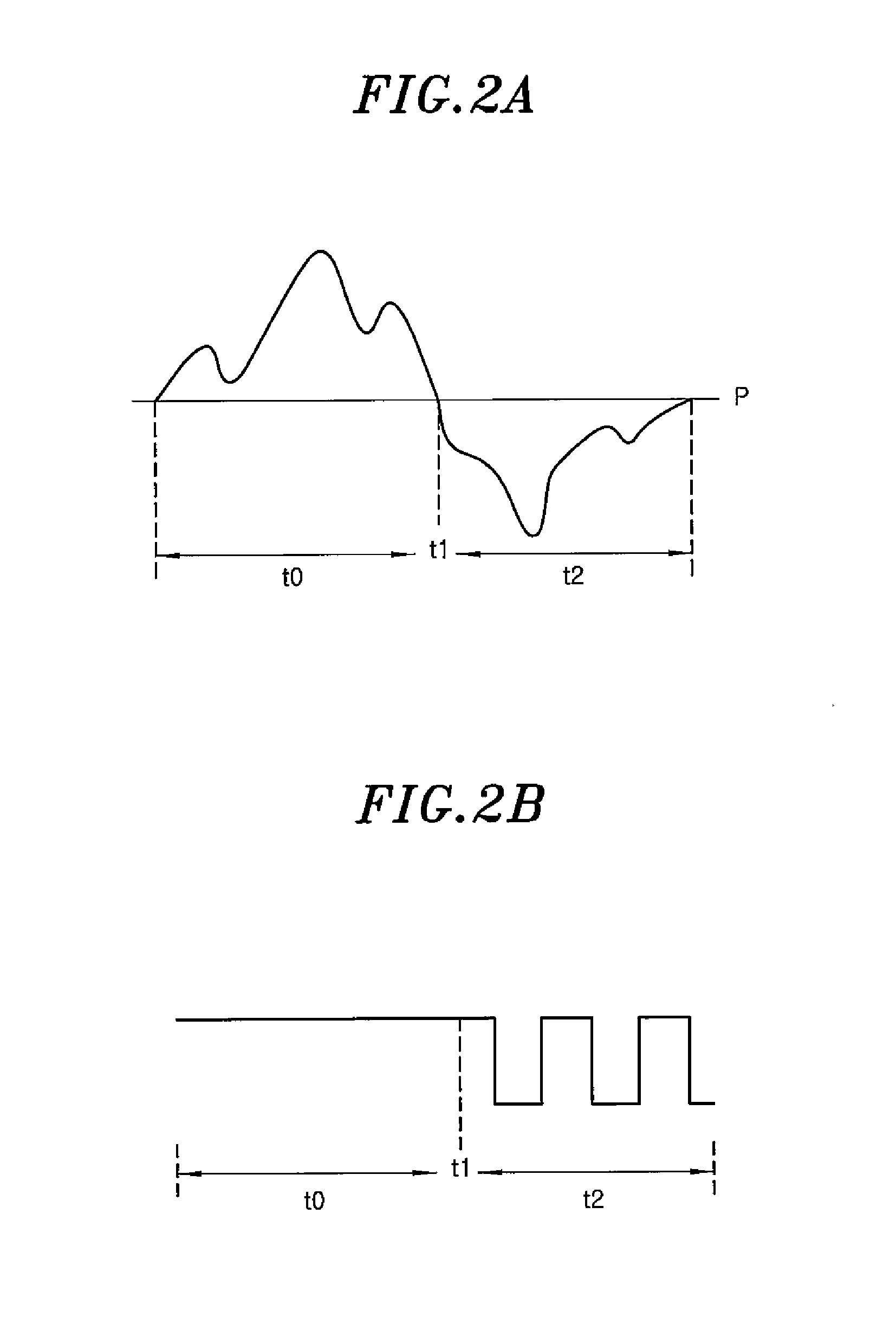
A signal amplification apparatus includes a first modulator configured to receive an envelope signal, use a predetermined reference level to separate the received envelope signal into a first period and a second period, digitally modulate a signal of the second period to output the digitally modulated signal to a first output terminal, and output a signal of the first period to a second output terminal. Further, the signal amplification apparatus includes a second modulator configured to mix the digital modulated signal input through the first output terminal with a phase modulated carrier signal; an envelope modulator configured to output the signal of the first period as a power supply signal; and a power amplifier configured to amplify the mixed signal output by the second modulator to output the amplified signal.

Description

CROSS-REFERENCE TO RELATED APPLICATION(S)[0001]The present invention claims priority to and the benefit of Korean Patent Application No. 10-2013-0081098, filed on Jul. 10, 2013, which is incorporated herein by reference.FIELD OF THE INVENTION[0002]The present invention relates to a transmission device in a communication system, and more particularly, to a signal amplification apparatus and method for realizing high efficiency of a power amplifier.BACKGROUND OF THE INVENTION[0003]Recently, a mobile communication system has evolved into a communication system based on orthogonal frequency-division multiplexing (OFDM) where the amplitude varies significantly unlike Global System for Mobile Communications (GSM). In particular, examples of the communication system based on OFDM include WiMAX and WLAN in addition to LTE.[0004]However, an OFDM based transmitter has a limitation in that its power amplifier does not work efficiently due to overcome the limitation, a variety of transmission s...

Claims


Application Information

Patent Timeline
Patent Type & Authority Patents(United States)
IPC IPC(8): H04B1/66H04W52/04H04W52/24H04W52/52H01Q11/12H04B1/04
CPCH04W52/04H04W52/241H04W52/52H03G3/20H04L27/26
Inventor JANG, SEUNGHYUNLEE, SUNG JUNCHO, YOUNG KYUNPARK, BONG HYUKJUNG, JAE HOLEE, KWANGCHUN
Owner ELECTRONICS & TELECOMM RES INST
Learn More