AI technical title is built by Patsnap AI team. It summarizes the technical point description of the patent document.
a cutting device and optical blade technology, applied in the field of optical blades and hair cutting devices, can solve the problems of limited manipulation, skin irritation, hair pulling effect, etc., and achieve the effect of improving the balance of closeness versus irritation and improving hair-skin manipulation
Active Publication Date: 2016-03-29
KONINKLIJKE PHILIPS ELECTRONICS NV
View PDF27 Cites 2 Cited by
Summary
Abstract
Description
Claims
Application Information
AI Technical Summary
This helps you quickly interpret patents by identifying the three key elements:
Problems solved by technology
Method used
Benefits of technology
Benefits of technology
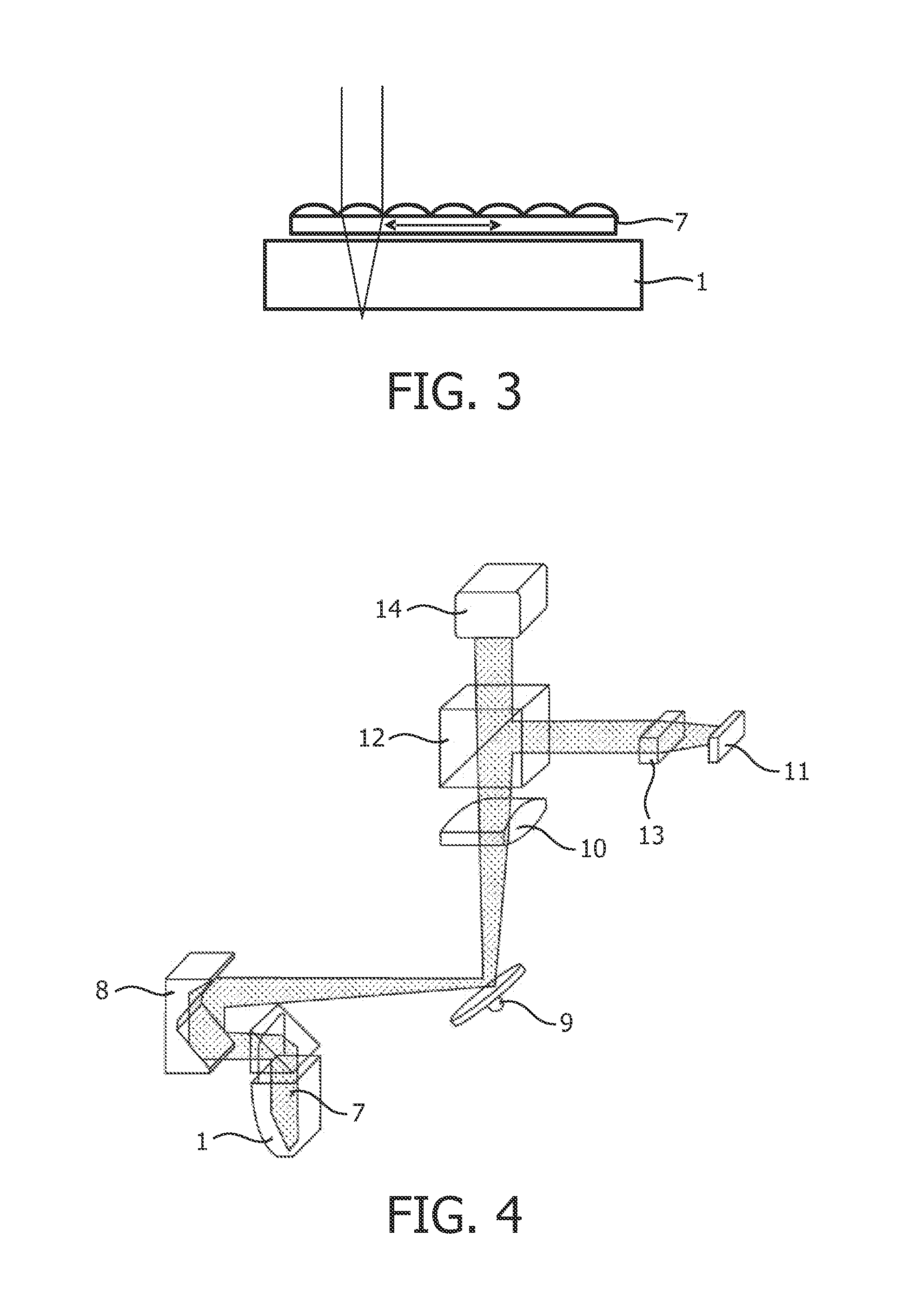
The invention aims to improve the balance of closeness and irritation in blade-based shaving systems. It achieves this by using an optical blade that can manipulate hair and optionally cut it. A detector is used to detect the presence of hair, allowing for optional cutting. The focusing characteristics of the optical blade are maintained even in the presence of water, shaving additives, and skin residues. The optical blade has a hollow cylindrical meniscus lens and a focusing structure that ensures the laser beam remains focused on the hair to be cut, regardless of external changes. The optical blade is made using a molding process and has a curved focusing surface that provides an accurate position for hair cutting.
Problems solved by technology
For each of the methods described the amount of manipulation is limited due to the limitations imposed by the desire to maintain the integrity of the skin and to preserve the comfort during the shaving process.
For instance, for blade shavers it is important to limit the amount of force required for hair cutting since otherwise the hair-pulling effect becomes highly uncomfortable, even though it might lead to improved closeness.
For significant skin manipulation in, for instance, a foil or rotating shaving system, a high amount of local skin pressure is required which would result in extreme requirements for the force exerted by the device, and, hence, by the user on her / his skin, which would lead to excessive skin doming through holes and slots into the cutting chamber, resulting in skin irritation.
The retraction means of rotating shaving systems is limited on account of the required acceleration of the hairs which is in the order of 1000 g and by the probability of correctly catching and retracting each hair.
However, a problem associated with each of the aforementioned techniques is that the processes of manipulation of hair and skin are performed with commonly the same means that are used to eventually cut the hairs, thus significantly limiting the amount of manipulation that can be employed, making the manipulation techniques sub-optimal.
In addition, in each of the methods mentioned, the cutting process is non-optional, i.e. if an object is presented in front of a blade or inside the cutting chamber it will be cut, irrespective of whether it is actually being manipulated properly or whether it is a hair at all.
Method used
Image
Click on the blue label to locate the original text in one second.
Reading with bidirectional positioning of images and text.
Examples
Embodiment Construction
[0039]The optical blade according to the invention preferably comprises a number of different functionalities relating to its mechanical, geometrical and optical properties, which are going to be described in the following. According to a first preferred embodiment of the invention, the material of the optical blade is transparent to the wavelength of the light that is used for the detection unit as well as for the cutting unit. The material is preferably capable of withstanding the considerable intensity used in the cutting laser. In addition, it preferably does not introduce strong birefringence in order to avoid difficulties in the hair detection process. Depending on the wavelength of the light used, the optical blade is preferably manufactured from glass in any arbitrary shape using e.g. glass molding or diamond turning techniques or, according to other preferred embodiments of the invention, using specialty plastics, such as cyclo-olefin polymers combined with injection moldin...
PUM
Abstract
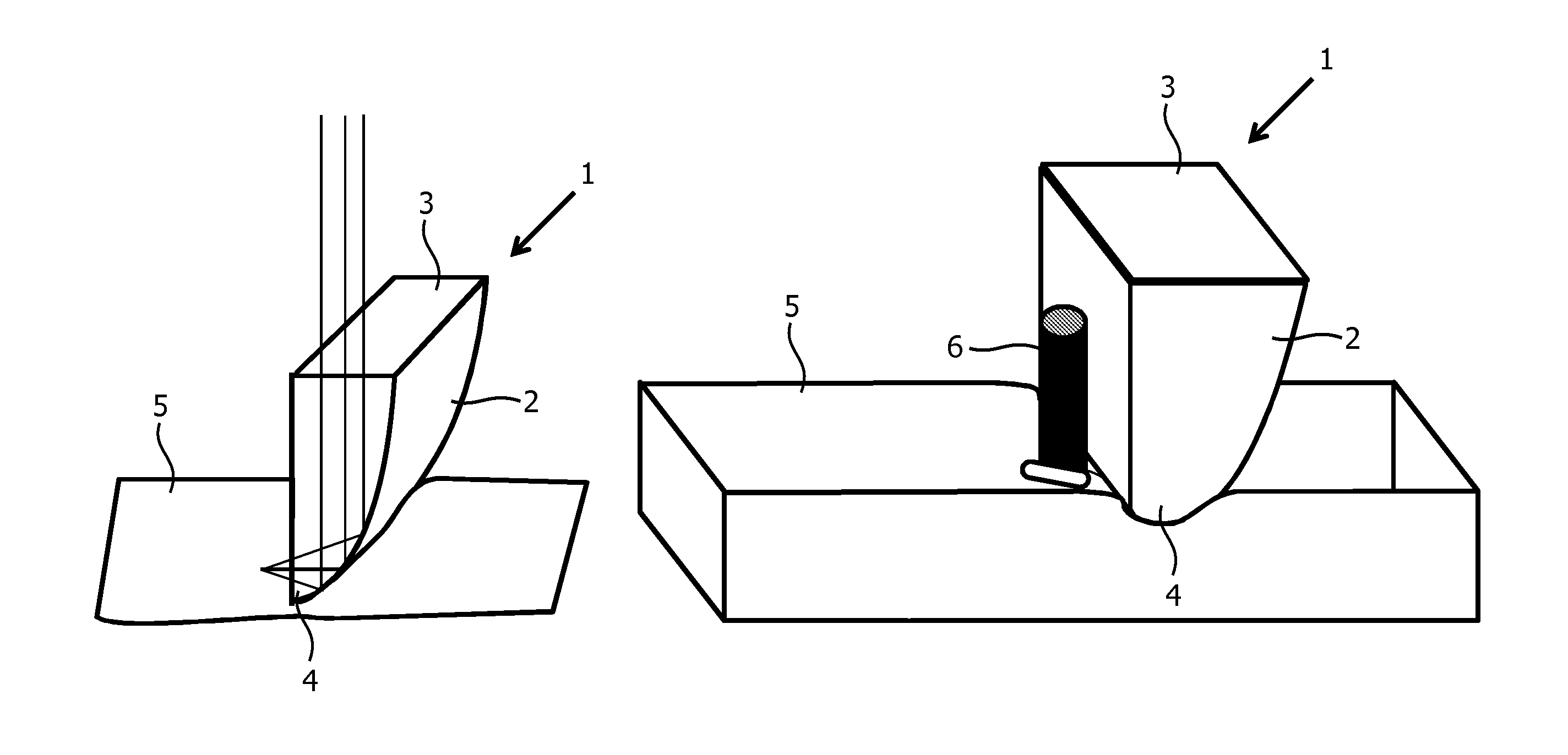
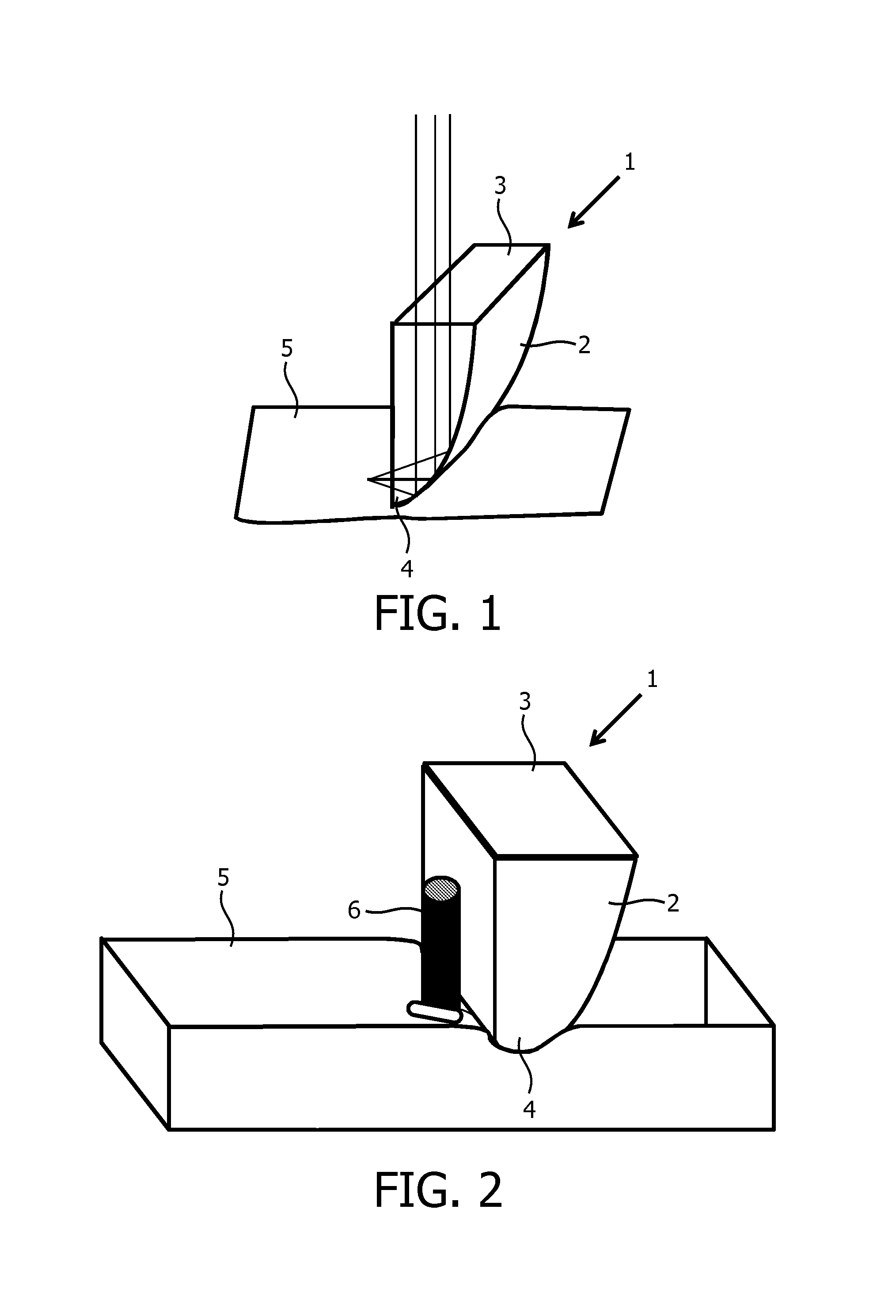
An optical blade and a hair cutting device is configured to cut a hair near skin of a human body part or animal body part. The optical blade maybe used in a hair cutting device and includes a blade body configured to guide optical radiation, and a tapered end configured to allow the optical radiation to exit the optical blade. The tapered end includes a reflector configured to redirect the optical radiation before it exits the optical blade.
Description
FIELD OF THE INVENTION[0001]The invention relates to an optical blade and a hair cutting device, preferably adapted for cutting a hair near skin of a human body part or animal body part. The invention also relates to a method of use for a hair cutting device.BACKGROUND OF THE INVENTION[0002]Document WO 2008 / 115899 A2 describes a compact and portable optical shaving device which cuts hair shafts using electromagnetic radiation. According to a preferred embodiment, the optical shaving device includes a power source that connects to one or more optical components. An optical device, such as an optical blade, can connect to and aligns with the array of optical components. The optical component(s) can provide light to the optics based on electrical energy from the power source. The optical component(s) or the optics can manipulate and direct the electromagnetic radiation to cut the hair shafts.[0003]Classical shaving methods used commonly for the removal of facial and / or body hair employ...
Claims
Application Information
Patent Timeline
Application Date:The date an application was filed.
Publication Date:The date a patent or application was officially published.
First Publication Date:The earliest publication date of a patent with the same application number.
Issue Date:Publication date of the patent grant document.
PCT Entry Date:The Entry date of PCT National Phase.
Estimated Expiry Date:The statutory expiry date of a patent right according to the Patent Law, and it is the longest term of protection that the patent right can achieve without the termination of the patent right due to other reasons(Term extension factor has been taken into account ).
Invalid Date:Actual expiry date is based on effective date or publication date of legal transaction data of invalid patent.

