
Knit article of apparel and apparel printing system and method

a printing system and knitting technology, applied in knitting, transfer printing, textile treatment by spraying/projecting, etc., can solve the problems of affecting the appearance of printed designs on knit fabrics, and difficult to print on three-dimensional or tubular knit textiles

Active Publication Date: 2016-03-29
NIKE INC
View PDF35 Cites 19 Cited by
  • Summary
  • Abstract
  • Description
  • Claims
  • Application Information

AI Technical Summary

Benefits of technology

The patent describes a system and method for printing on apparel with a tubular knit textile region. The text describes the configuration of the textile region, including its arrangement of interlocked loops and channels, and the ink design that can be applied to it. The system includes a textile printer with a print head and a tubular platen for holding the textile during printing. The technical effects of the invention include improved printing precision and efficiency, as well as the ability to print on a wider range of textile materials.

Problems solved by technology

For example, it is difficult to print on three-dimensional or tubular knit textiles for reasons such as difficulties with retaining and registering them to create quality prints due to the knit fabric being created in a non-planar configuration.
As another example, the appearance of printed designs on knit fabrics is often diminished by the lack of ink being applied to yarns below the viewable surface during printing, which can become visible during use of the fabric due to flexing and stretching of the fabric and, thereby, interfere with the appearance of the printed design.

Method used


Image

  • Knit article of apparel and apparel printing system and method
  • Knit article of apparel and apparel printing system and method
  • Knit article of apparel and apparel printing system and method

Examples


example configurations

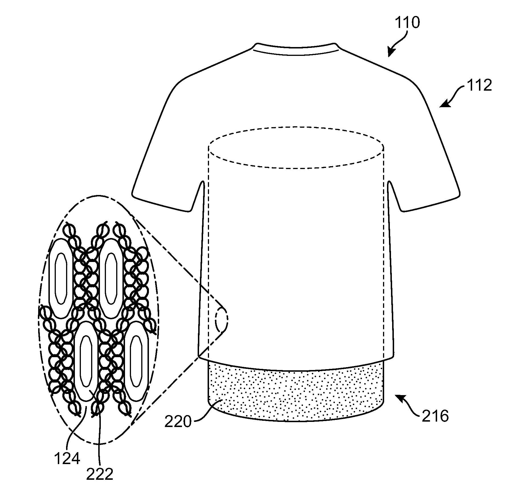
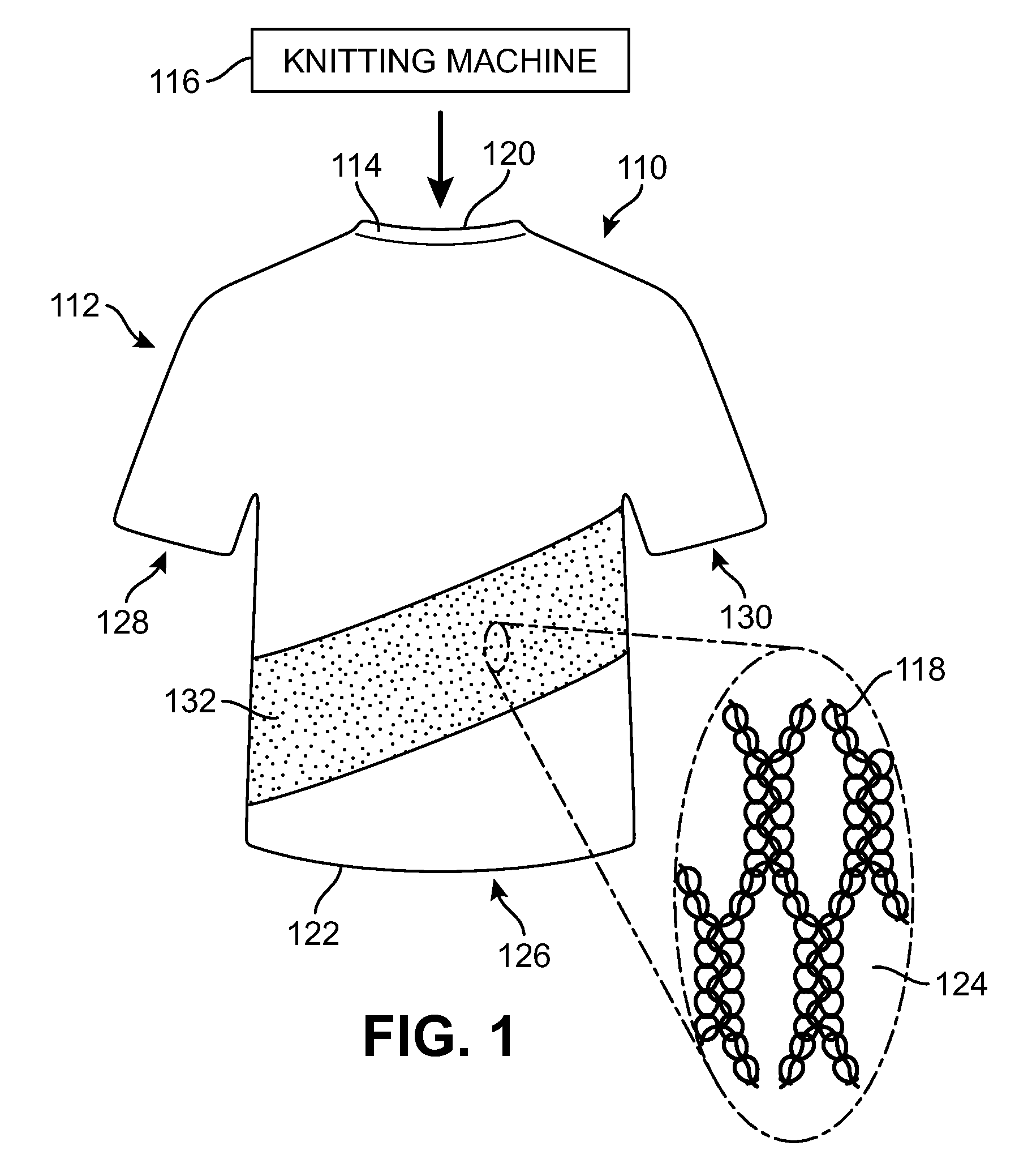
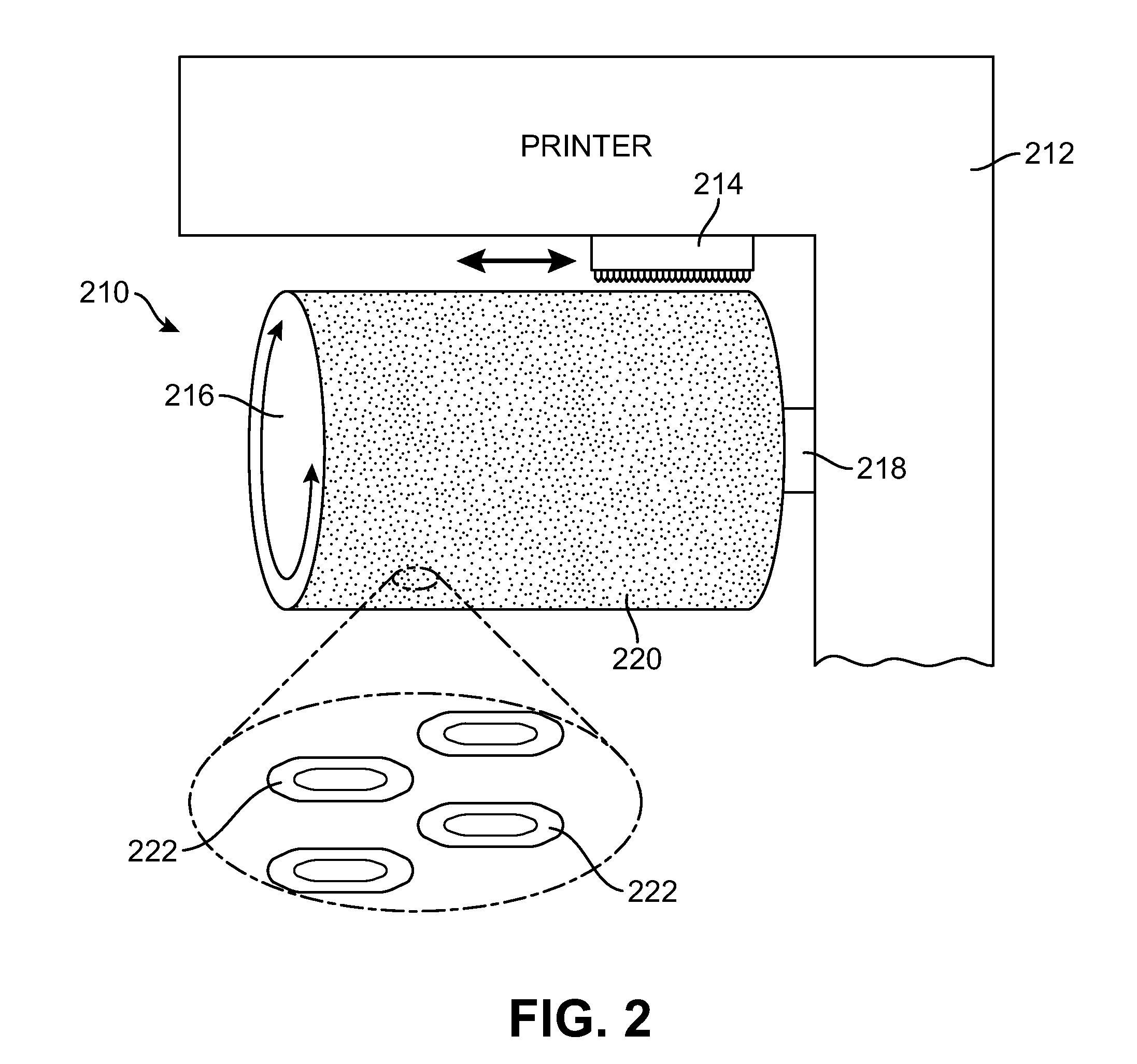
[0040]FIGS. 3, 4, 5A and 5B depict example configurations of an article of apparel 110 including a tubular knit region 112, a tubular platen 216 and features for orienting, registering and / or retaining tubular knit region 112 on tubular platen 216 for printing a graphical design on the tubular knit region. These configurations are generally the same as those discussed previously along with FIGS. 1 and 2 except as discussed hereafter. As shown in FIG. 3, the tubular knit region 112 of article of apparel 110 can be placed on tubular platen 216 by guiding waist opening 126 over the unsupported end of tubular platen 216 such that the interior side of tubular knit region 112 is in contact with platen surface 220. A stop line (not shown) or other marking can be placed on the platen surface 220 to indicate how far to advance tubular knit region 112 over tubular platen 216. Tubular knit region 112 can be advanced as far as needed for printing and can be arranged on platen surface 220 such t...


PUM

PropertyMeasurementUnit
Diameteraaaaaaaaaa

Abstract

An article of apparel including a tubular knit textile region is provided, as well as an apparel printing system for printing on regions of the tubular knit textile region and related methods. The article of apparel can include a tubular knit textile region having an internal side and an opposite external side configured to be exposed during use, a plurality of yarns in an arrangement of interlocked loops forming parallel rows and channels therebetween, and a printed ink design on its external side. The printed ink design can be formed from ink applied to the parallel rows of loops and to the channels. An apparel printing system for printing on the article of apparel can include a textile printer having a print head and a tubular platen that includes features on the platen surface to retain and register the tubular knit textile on the platen surface during printing.

Description

BACKGROUND[0001]Articles of apparel employ various fabrics in countless arrangements for reasons such as aesthetics, structural and functional purposes, and for comfort. Knit fabrics are often used in articles of apparel to provide advantages such as greater elasticity or stretch in one or more directions, to provide features for the user like increased warmth and comfort, and to provide performance features like resistance to wrinkles and good performance in wet and dry wet conditions. In addition to these advantages, knit fabrics are increasingly being used for commercial advantages like their ease of manufacturing via the use of commercial knitting machines.[0002]The use of commercial knitting machines can allow fabrics and articles of manufacture using knit fabrics to be made in high volumes that use intricate knitting designs for their construction. In addition, the use of such machines can permit large portions of an article of apparel, and even the entire article of manufactu...

Claims


Application Information

Patent Timeline
IPC IPC(8): B41J3/407D04B1/24D06H1/02B41F15/18B41F16/02B41F17/00B41F17/38
CPCB41F15/18B41F16/02B41F17/003B41F17/005B41J3/4078D06H1/02D04B1/24A41D2500/10B41P2217/60D04B21/207B41J11/04D06B11/0073D06B1/02D04B1/246
Inventor TURNER, DAVID
Owner NIKE INC
Learn More