Method for improving wellbore survey accuracy and placement

a wellbore and survey accuracy technology, applied in the field of subterranean can solve the problems of limited survey accuracy, significant placement errors, and corresponding wellbore orientation and placement errors, and achieve the effect of improving wellbore survey accuracy and placemen

Inactive Publication Date: 2016-03-29
SCHLUMBERGER TECH CORP
View PDF13 Cites 3 Cited by
  • Summary
  • Abstract
  • Description
  • Claims
  • Application Information

AI Technical Summary

Benefits of technology

[0008]The disclosed embodiments may provide various technical advantages. For example, disclosed methods tend to improve wellbore survey accuracy and placement as compared to conventional wellbore surveying procedures. Disclosed embodiments may also be utilized to improve the accuracy of subterranean magnetic ranging operations.

Problems solved by technology

The accuracy of the survey is limited by the accuracy of this “known” magnetic field.
The accuracy of the “known” field strength, magnetic declination, and magnetic inclination is directly related to survey accuracy with errors in these parameters resulting in corresponding wellbore orientation and placement errors.
The placement errors can be significant (especially in deep wells) as they compound from one survey measurement to the next.
The historical survey data and geomagnetic models tend to be limited in that they do not account for local magnetic field variations and solar magnetic activity.
Even at low latitudes (e.g., near the equator), the magnetic declination and magnetic inclination estimated using geomagnetic models can have errors approaching one degree.
Such errors can result in significant borehole azimuth errors, for example, in a nearly horizontal, east-west wellbore, the magnetic azimuth error can be greater than four degrees.
Moreover, these errors tend to be systematic (non-random) and can result in wellbore placement errors on the order of 100 feet or more in deep wells.
Measurement of the Earth's magnetic field at the surface while drilling is generally considered not to be practical or reliable, for example, due to local magnetic interference at the rig site.
The oil industry has generally chosen to accept the aforementioned errors and the corresponding poor survey and well placement results.

Method used


Image

  • Method for improving wellbore survey accuracy and placement
  • Method for improving wellbore survey accuracy and placement
  • Method for improving wellbore survey accuracy and placement

Examples


Embodiment Construction

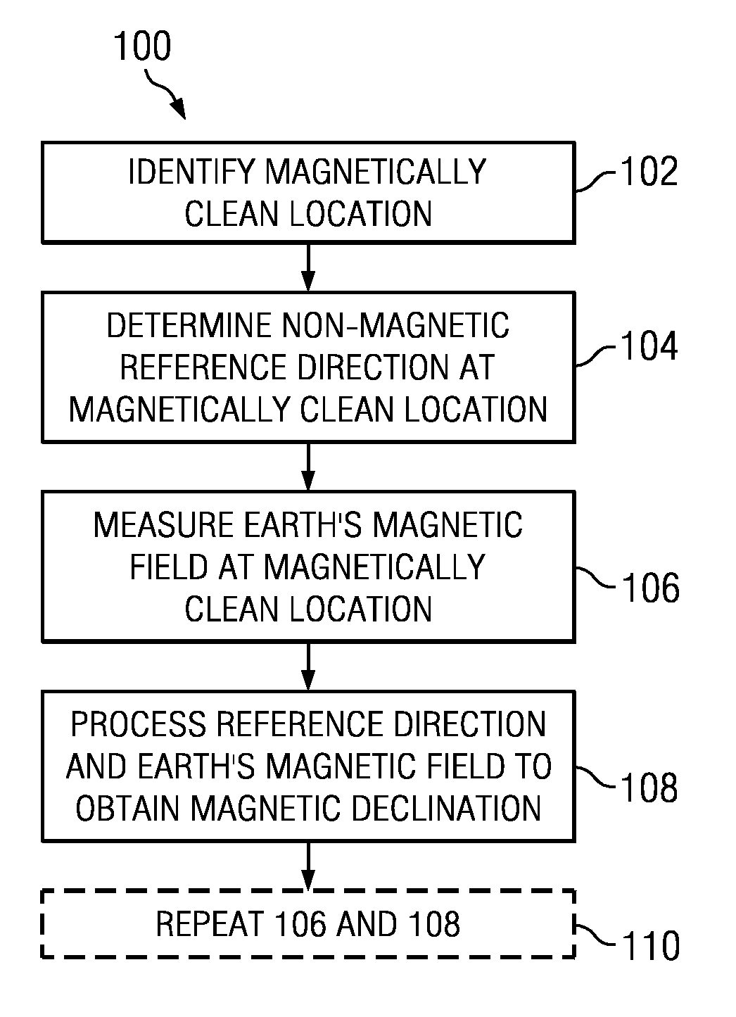
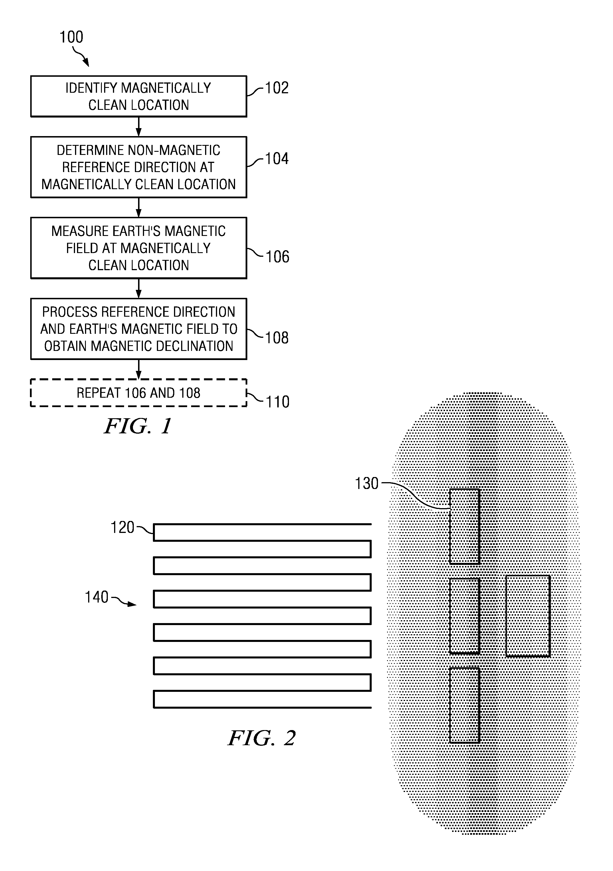
[0015]FIG. 1 depicts a flow chart of method embodiment 100. At 102 a magnetically clean area is identified close to the rig site. This may be accomplished, for example, via a proton magnetometer scan as described in more detail below. A non-magnetic reference direction is then determined in the magnetically clean area at 104. The reference direction may be determined, for example, via global positioning system (GPS) measurements or conventional gyro measurements as is also described in more detail below. At 106, the Earth's magnetic field is measured in the magnetically clean area, for example, using a tri-axial magnetometer package substantially identical to that used in wellbore surveying operations. At 108 the nonmagnetic reference direction determined at 104 and the magnetic field measured at 106 are processed in combination to obtain magnetic declination and magnetic inclination. Steps 104, 106, and 108 (or steps 106 and 108) may optionally be repeated at substantially any time...


PUM


Abstract

Methods for improving wellbore survey accuracy and placement are disclosed. The Earth's magnetic field may be measured at a magnetically clean surface location and correlated with a non-magnetic reference direction to obtain a direction of the Earth's field (e.g., a magnetic declination or a magnetic inclination). The direction of the Earth's magnetic field may in turn be processed in combination with magnetic measurements made in a subterranean borehole to obtain one or more survey parameters.

Description

CROSS REFERENCE TO RELATED APPLICATIONS[0001]This application claims the benefit of U.S. Provisional Application Ser. No. 61 / 502,464 entitled Method for Improving Wellbore Survey Accuracy and Placement, filed Jun. 29, 2011.FIELD OF THE INVENTION[0002]Disclosed embodiments relate generally to surveying subterranean wellbores used for oil and natural gas exploration and production. In particular, they relate to a method for improving survey accuracy via an improved measurement of the Earth's magnetic field (e.g., including total magnetic flux, magnetic inclination, magnetic declination).BACKGROUND INFORMATION[0003]In conventional well drilling operations, surveying measurements are made both during and after drilling. The surveying measurements are used to determine both the orientation and absolute position of the well bore. The wellbore survey is often determined in part from measurements of the Earth's magnetic field in the wellbore. The measured magnetic field may be processed, fo...

Claims


Application Information

Patent Timeline
Patent Type & Authority Patents(United States)
IPC IPC(8): E21B47/22G01V3/40E21B47/022
CPCE21B47/02224E21B47/022G01V3/40E21B47/0232
Inventor MCELHINNEY, GRAHAM, A.CEH, LEONFORBES, EUANSTENERSON, KENNETH
Owner SCHLUMBERGER TECH CORP
Why Eureka
Try Eureka