
Probe

a probe and probe body technology, applied in the field of probes, can solve the problems of high price of platinum, achieve the effects of reducing the significance of impedance, reducing the overall size of the probe, and reducing the distan

Active Publication Date: 2016-03-29
ABER INSTR
View PDF8 Cites 0 Cited by
  • Summary
  • Abstract
  • Description
  • Claims
  • Application Information

AI Technical Summary

Benefits of technology

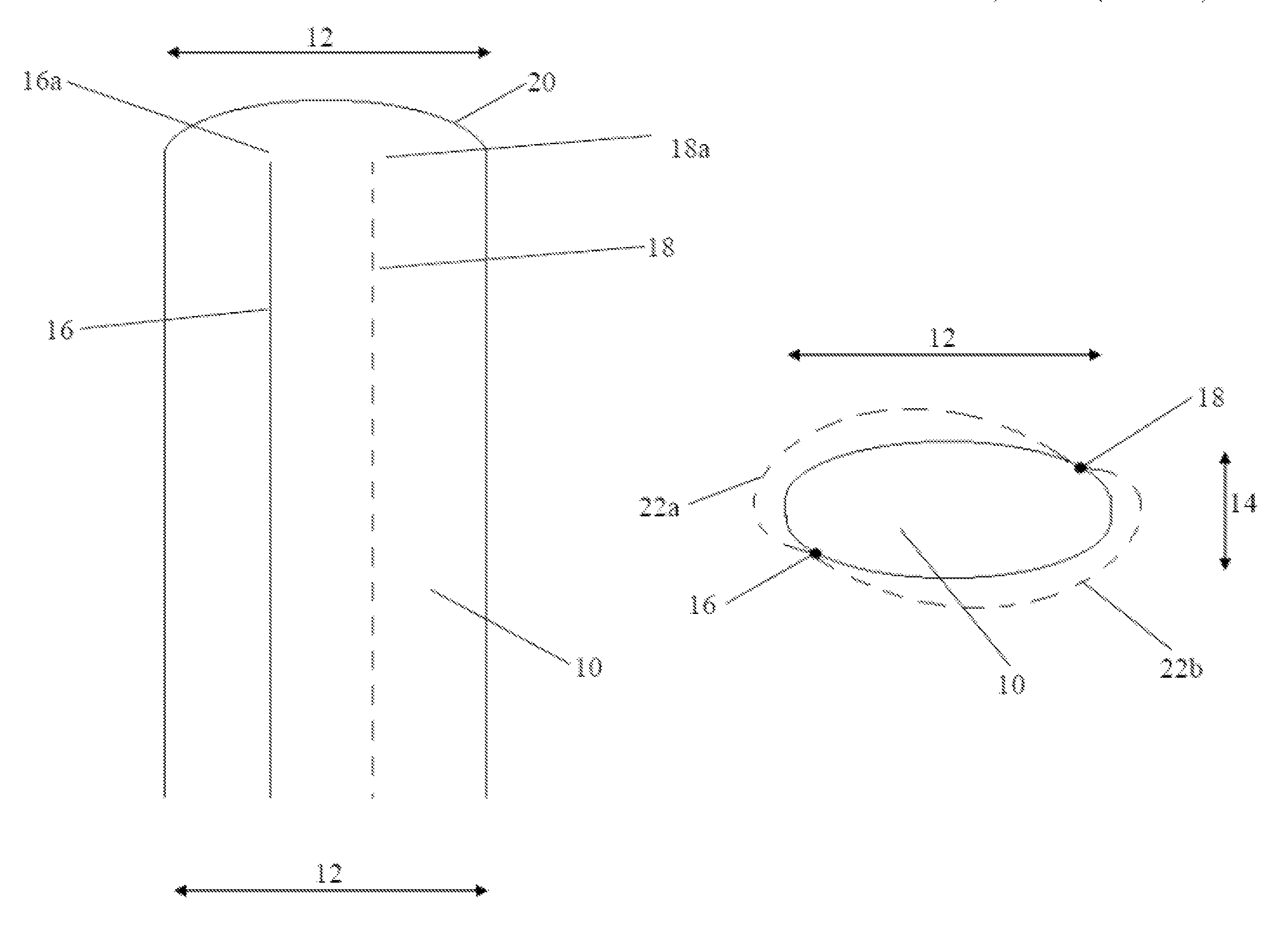
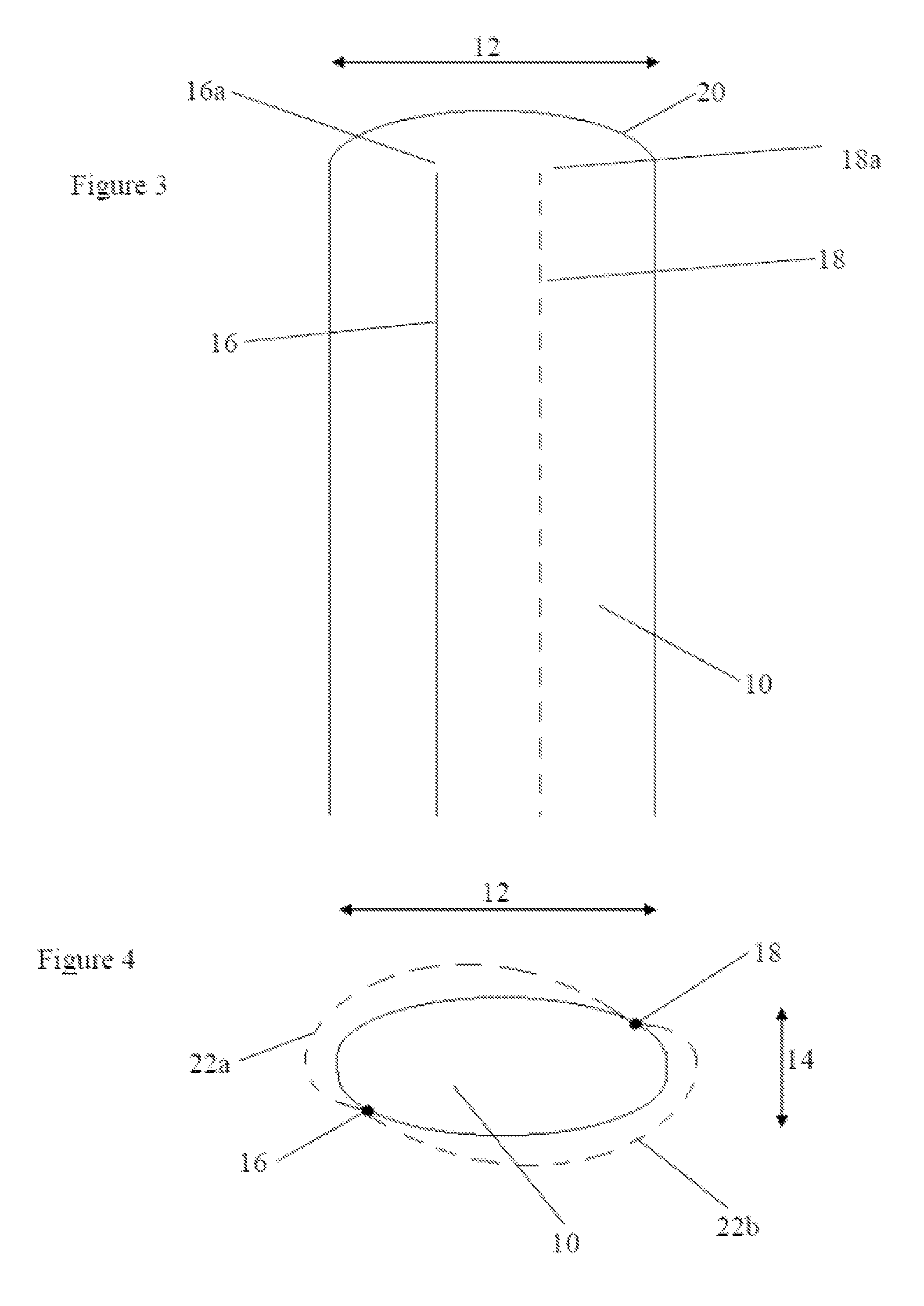
[0013]Such an arrangement provides significant advantages over the prior art. A significant advantage of the presently claimed invention is the separation distance between the electrodes thereby reducing the significance of the impedance between the electrode and the liquid. By increasing this distance through the design of the probe body, the overall size of the probe can be reduced as can be the materials for production of the probe. This is particularly important as platinum electrodes are typically used for critical measurements which have also been shown to reduce polarization impedance. However, platinum is extremely expensive and thus reduction in the amount required for use is extremely beneficial, significantly reducing costs whilst also maintaining the functional benefits.
[0014]End points beneficially define the length of the body portion in the major axis, wherein the first and second electrodes are positioned such that the current flow path between the first and second electrodes is around an end point of the length of the body portion of the major axis and / or around a distal end of the probe body. As such, even though the first and second electrodes are effectively separated by a small distance through the provision of the body portion of the probe, the body portion of the probe has insulating properties meaning that the current flow path is around an end point of the body portion of the major axis. The effective separation between the first and second electrodes is therefore significantly increased thereby reducing the influence on the measured impedance value through the polarization effect between the current carrying electrodes and the medium under investigation.
[0015]The first and second electrodes are beneficially positioned either side of the minor axis. This improves manufacturing capability and also maximizes separation between first and second electrodes. Separation is effectively maximized in this manner by maximizing the current path between the electrodes around the tip of the probe body. By positioning the first and second electrodes on either side of the minor axis, the electrode separation is increased over the probe body tip.
[0016]The first and second electrodes beneficially extend generally parallel to the longitudinal axis of the probe. Furthermore, the electrodes are beneficially substantially linear. This provides manufacturing advantages in that no kinks or turns are required in the electrodes. It is of significant benefit to offset the electrodes in this manner as the electrodes can then be in a straight line making it easier to connect them to a PCB in the probe body. Additionally, a lack of kinks or turns in the electrodes means that less material is used. Electrode material is typically extremely expensive when accurate measurement is required meaning that a reduction in material provides significant cost savings.
[0017]The probe body beneficially extends to a tip. The electrodes beneficially extend toward but not to the tip. The tip therefore beneficially extends or projects beyond the distal ends of the electrodes. This provides a significant advantage in that the electrodes are protected by the body portion of the probe and also ensure that the separation between the electrodes over the tip of the probe is of sufficient separation.

Problems solved by technology

However, platinum is extremely expensive and thus reduction in the amount required for use is extremely beneficial, significantly reducing costs whilst also maintaining the functional benefits.

Method used


Image

  • Probe
  • Probe
  • Probe

Examples


Embodiment Construction

[0031]To facilitate an understanding of the principles and features of the various embodiments of the invention, various illustrative embodiments are explained below. Although exemplary embodiments of the invention are explained in detail, it is to be understood that other embodiments are contemplated. Accordingly, it is not intended that the invention is limited in its scope to the details of construction and arrangement of components set forth in the following description or illustrated in the drawings. The invention is capable of other embodiments and of being practiced or carried out in various ways. Also, in describing the exemplary embodiments, specific terminology will be resorted to for the sake of clarity.

[0032]It must also be noted that, as used in the specification and the appended claims, the singular forms “a,”“an” and “the” include plural references unless the context clearly dictates otherwise. For example, reference to a component is intended also to include composit...


PUM

PropertyMeasurementUnit
longitudinal lengthaaaaaaaaaa
cross-sectional areaaaaaaaaaaa
lengthaaaaaaaaaa

Abstract

An improved probe designed in particular but not exclusively for measuring the concentration of live biomass. The probe has an insulating body portion arranged to carry a first and second electrode where the probe has a longitudinal axis and the first and second electrodes extend in this longitudinal axis. The body portion has a cross-sectional area perpendicular to the longitudinal axis defined by a major axis and minor axis, wherein the length of the body portion in the major axis is greater than the length of the body portion in the minor axis. The first and second electrodes are positioned on either side of the major axis. This reduces the effect of impedance between the electrode and the liquid through increasing the effective distance between the electrodes.

Description

CROSS-REFERENCE TO RELATED APPLICATIONS[0001]This application claims the benefit under 35, U.S.C. §119(a)-(d) and (f) of GB 1219078.1, filed 24 Oct. 2012, the entire contents and substance of which is hereby incorporated by reference.BACKGROUND OF THE INVENTION[0002]1. Field of Invention[0003]The present invention relates to an improved probe. The probe has been designed in particular but not exclusively for measuring the concentration of live biomass.[0004]2. Background and Related Art[0005]Capacitance measurement techniques are known for measuring the capacitance (or specific capacitance or dielectric constant) of liquids and suspensions, such as biological cells in ionic aqueous solutions.[0006]Monitoring systems incorporating such measurement capability are beneficial for measuring concentration of live cells. In particular in the brewing industry, the concentration of live yeast can be measured with an on-line capacitance probe. A radio frequency applied from the electrodes of ...

Claims


Application Information

Patent Timeline
Patent Type & Authority Patents(United States)
IPC IPC(8): G01N27/22C12M1/34
CPCG01N27/221C12M41/36G01N27/226G01N33/48735G01N27/07
Inventor AGATE, LINDSAY
Owner ABER INSTR
Learn More