Lightweight reduction gearbox

a gearbox and light weight technology, applied in the direction of gearing details, gearing, transportation and packaging, etc., can solve the problem of critical weight of the gearbox, and achieve the effect of reducing the importance of compactness or space saving and high numerical reduction ratio

Active Publication Date: 2009-03-10
KAREM AIRCRAFT INC
View PDF22 Cites 12 Cited by
  • Summary
  • Abstract
  • Description
  • Claims
  • Application Information

AI Technical Summary

Benefits of technology

[0007]The inventive subject matter provides devices and methods in which gearboxes combine a high numerical reduction ratio with the capability of transmitting power at a power-to-weight ratio previously unattainable with existing designs. A significant advantage is that such devices and methods lessen the importance of compactness or space savings.
[0010]This arrangement is especially suited to the driving of large propellers for turboshaft aircraft, or the rotors of large helicopters, because the space or volume constrains are of lesser importance than the weight of the assembled unit. A full assembly consists of a dividing gear set, which is the sun gear and first planets of the compound planet arrangement, and a combining gearbox which consists of the second planets and the output ring gear. In small scale, the dividing and combining gearbox sections and the interconnecting shafts could be co-located in a single housing, but in large scale aircraft or helicopters the separation of the two basic assemblies provides further advantages regarding immunity to structural deflections, drive redundancy, damage tolerance, access improvement, serviceability and weight reduction which are further discussed in detail.

Problems solved by technology

However, with propeller drives for aircraft or rotor drives for helicopters, weight of the gearbox is critically important.

Method used


Image

  • Lightweight reduction gearbox
  • Lightweight reduction gearbox
  • Lightweight reduction gearbox

Examples


Embodiment Construction

[0022]In the figures, the input sun gear is a parallel pinion, axially and radially located at a point remote from the operating plane of the pinion, but with angular freedom such that the pinion can occupy the precise position whereby it is in balance between the tooth contact forces.

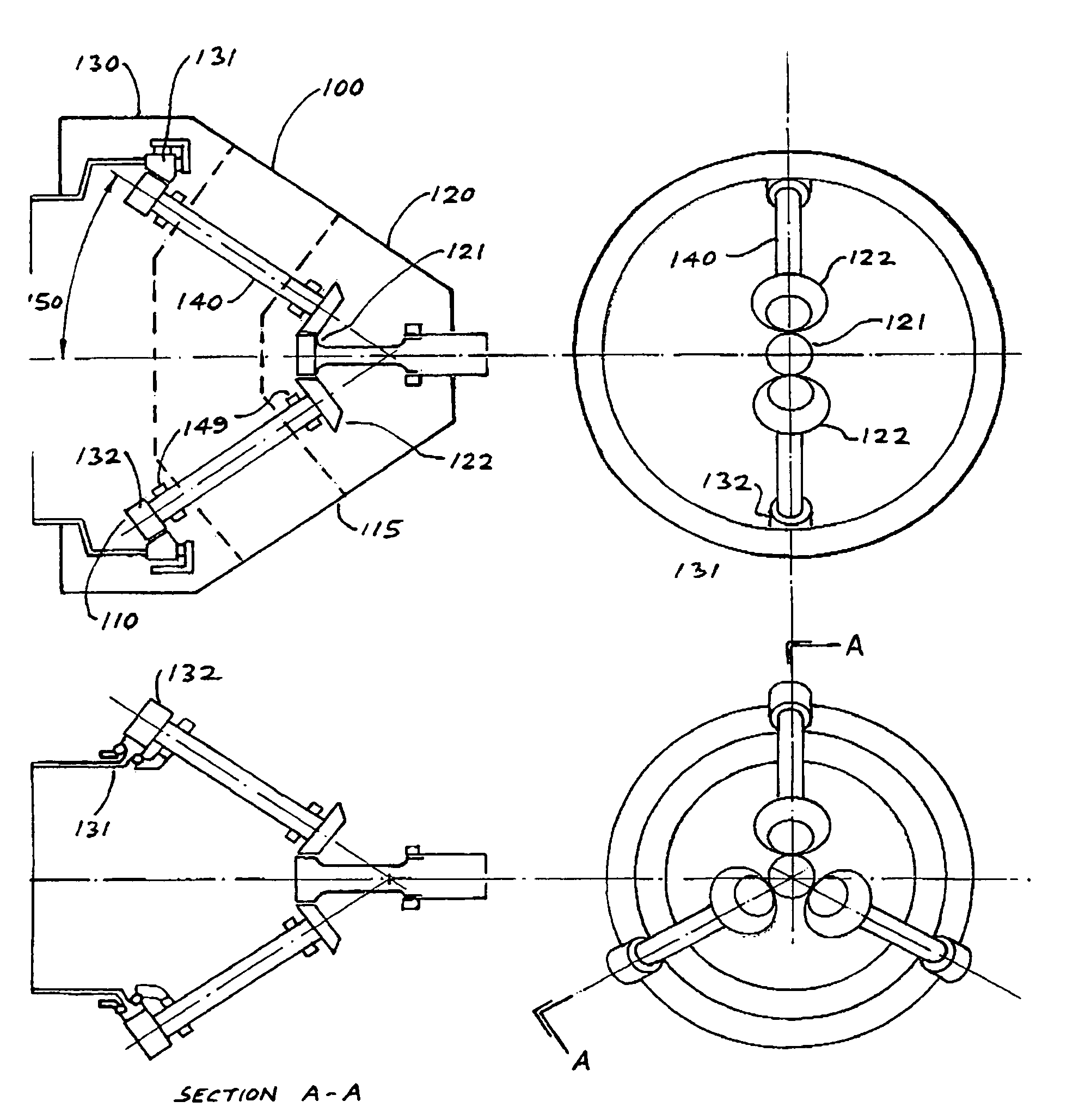
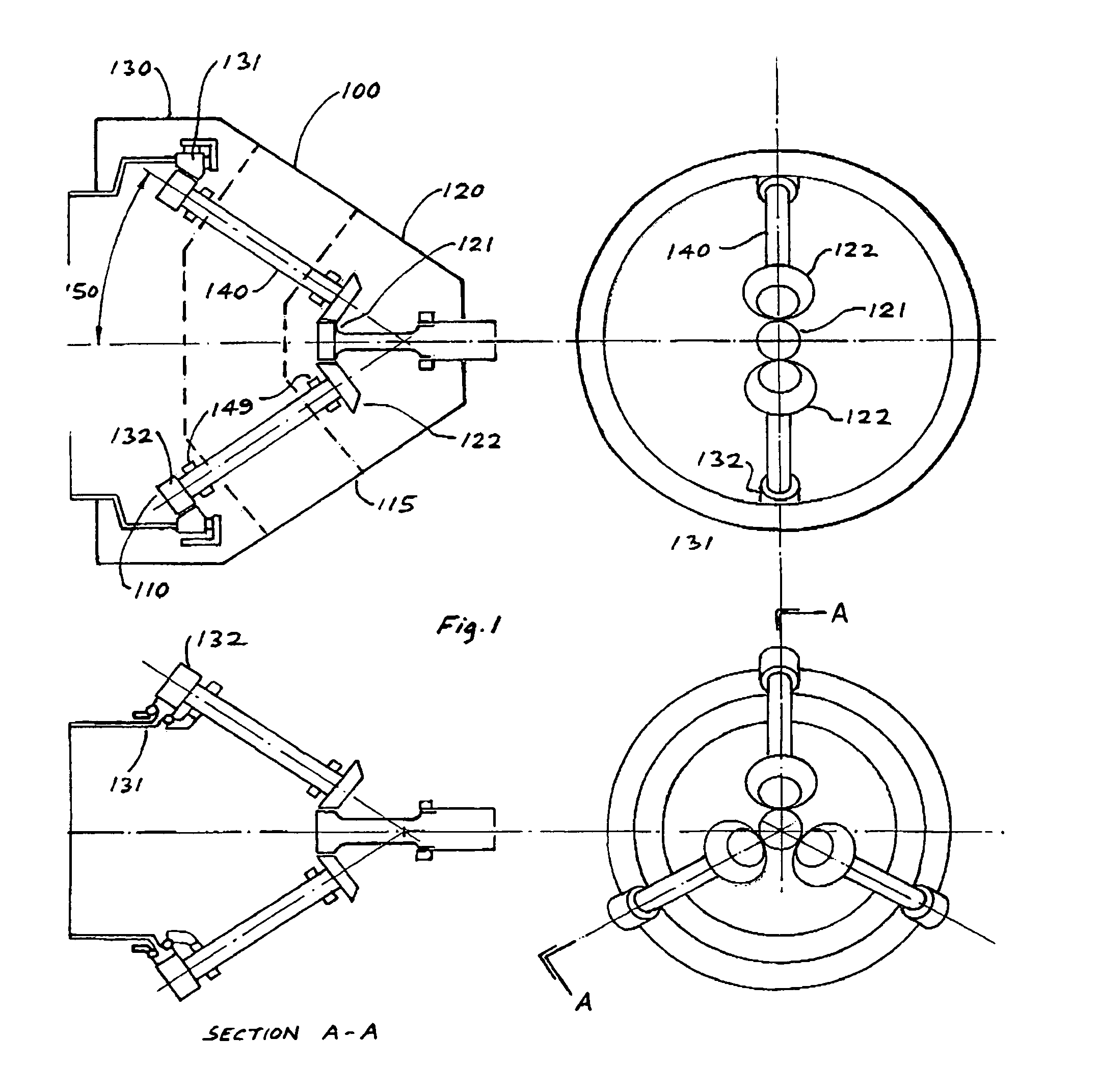
[0023]In FIG. 1, a reduction gearbox 100 generally comprises a radially expanded compound planetary gear set 110 in a casing 115, that has a distributor portion 120 and a combining portion 130. The distributor portion 120 generally comprises a sun gear 121 and several planet gears 122. The combining portion 130 generally comprises a driven ring gear 131 a further set of driving pinions 132. Connecting the distributor portion 120 and the combining portion 130 is an arrangement of multiple shafts 140 held in bearings 149.

[0024]Inclination 150 of the connecting shafts 140 relative to the principal axis of an input is a design choice. A larger angle (>45 deg.) results in relatively short assembly, however,...


PUM


Abstract

Contemplated gearboxes combine a high numerical reduction ratio with the capability of transmitting power at a superior power-to-weight ratio using a compound star planetary gearbox configuration that is radially expanded using hollow driveshafts to link the planet gears. In most preferred compound planetary gear arrangements, planets of different diameter are torsionally connected to each other, or mesh with each other. Input and output gears counter-rotate while the planets rotate in bearings anchored to a static casing.

Description

[0001]This application claims the benefit of our U.S. provisional patent application with the Ser. No. 60 / 694,024, which was filed Jun. 23, 2005.FIELD OF THE INVENTION[0002]The field of the invention relates to the transmission of power by gears.BACKGROUND OF THE INVENTION[0003]When gas turbine or turboshaft engines are employed to drive a plant, machinery, or a vehicle, a high numerical reduction ratio is frequently needed because of the output speed of the turbine. In addition, power transmission of several thousands of horsepower is encountered in many applications. In the case of a stationary plant, or for marine applications, mechanical reliability can be readily achieved if the weight of the gearbox is not important. However, with propeller drives for aircraft or rotor drives for helicopters, weight of the gearbox is critically important. This requirement led to the widespread adoption of planetary or epicyclic gearboxes in flight applications. Planetary gearboxes achieve thei...

Claims


Application Information

Patent Timeline
Patent Type & Authority Patents(United States)
IPC IPC(8): F16H57/08
CPCB64C27/14F16H1/227
Inventor WAIDE, WILLIAM MARTIN
Owner KAREM AIRCRAFT INC
Why Eureka
Try Eureka