
Interface pad for use between an abrasive article and a support tool

a technology for abrasive articles and support tools, which is applied in the direction of grinding drives, manufacturing tools, transportation and packaging, etc., can solve the problems of affecting the appearance and affecting the quality of the surface being abraded, so as to reduce the stock of abrasive articles and reduce the inventory of abrasive articles

Active Publication Date: 2009-09-17
SAINT GOBAIN ABRASIVES INC +1
View PDF25 Cites 17 Cited by
  • Summary
  • Abstract
  • Description
  • Claims
  • Application Information

AI Technical Summary

Benefits of technology

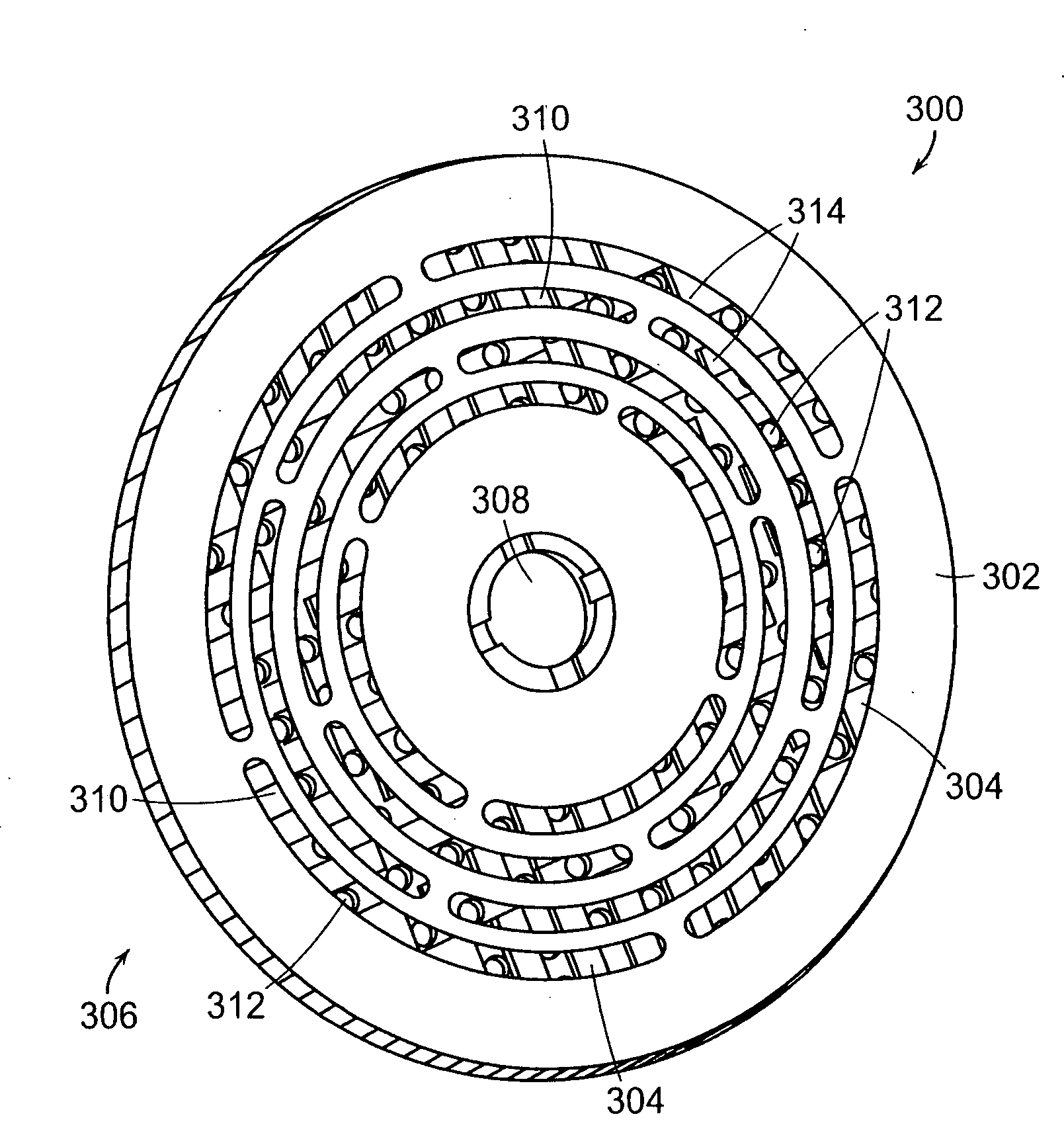
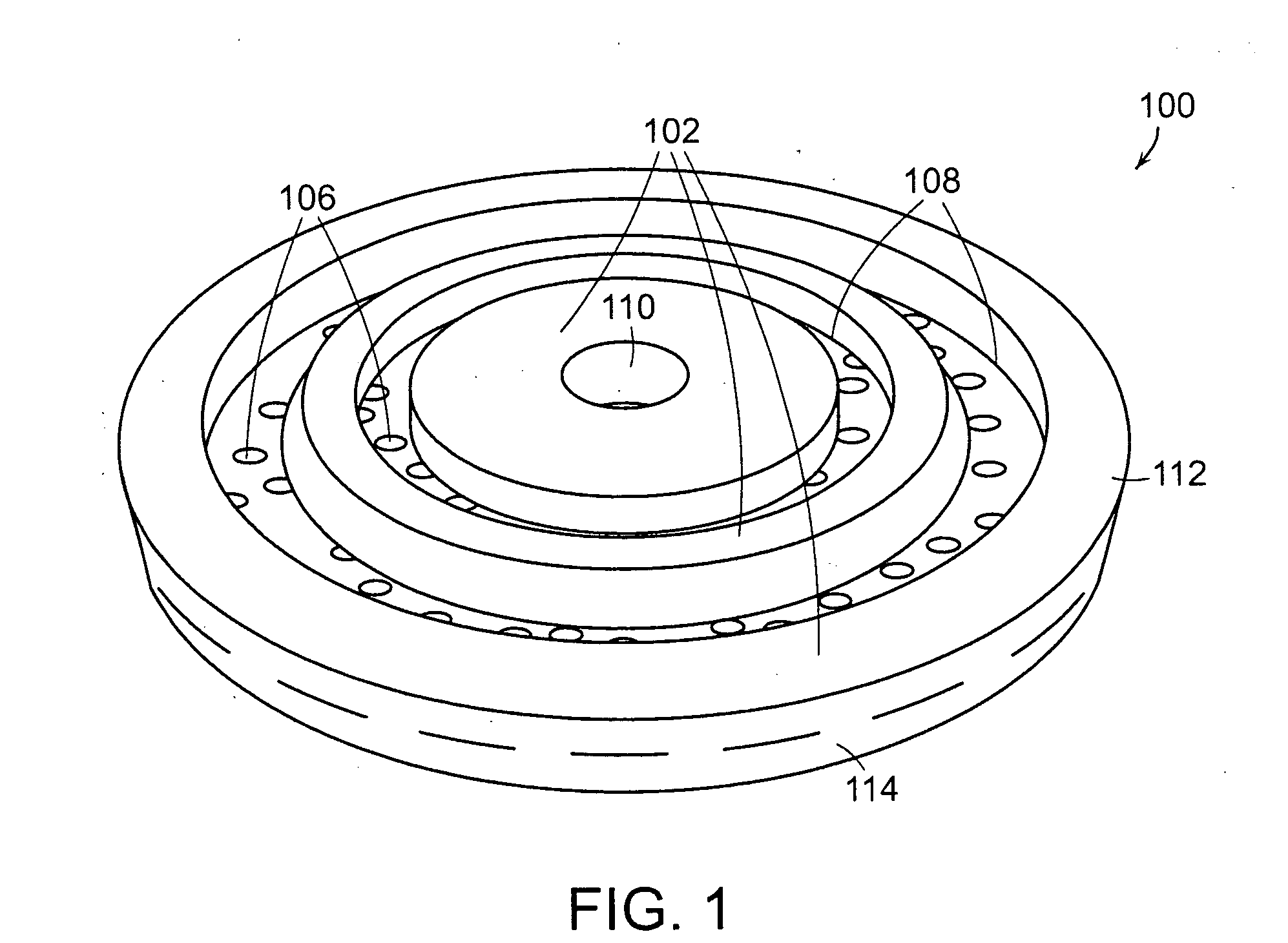
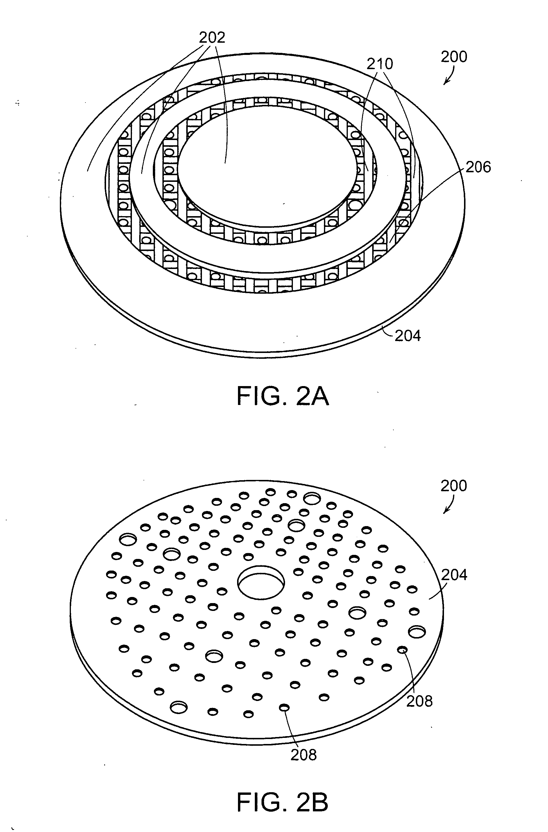
[0012]By using the interface pads described herein between an abrasive article and a support tool, abrasive articles that were previously not effective when used with certain support tools because of, for example, the difficulty or impossibility of sufficiently aligning perforations in the abrasive articles with dust collection holes in the support tool, can now be used effectively. The interface pads can provide a functional interface between the abrasive article and the support tool by permitting the flow of dust away from the work surface, through the interface pad, and into the dust collection system provided by the support tool. The interface pads described herein contain apertures and at least one channel configured such that an interface pad can be used between an abrasive article having a particular configuration of apertures and a support tool having a different configuration of dust collection apertures. In some instances, the interface pads described herein can be used between any perforated abrasive article and any support tool with dust extraction capabilities. Also, by practicing the present invention, improved dust extraction can be provided of an existing tool without permanent modification of the tool.
[0013]In some instances, the interface pad is configured such that the apertures of the interface pad do not need to be completely aligned with the apertures of the abrasive article or the support tool. When the interface pad is so configured, a user of the interface pad need not be concerned with properly orienting the interface pad with the abrasive article or the support tool. By permitting effective abrasion without precise alignment of the apertures, the present invention helps to reduce the significance of user error and helps to improve efficiency in commercial operations by reducing downtime and maintaining consistent abrasive performance.
[0019]Because the interface pads of the present invention can be used to join abrasive articles with support tools that were previously at least partially incompatible, the use of the interface pads can reduce the stock of abrasive articles or support tools that a user must keep on hand. In addition, stores that supply replacement abrasive articles and support tools can keep a reduced inventory of abrasive articles or support tools because of the universal inter-compatibility that the interface pads can provide.

Problems solved by technology

Abrasive articles can generate a great deal of dust, particularly when used on wood.
This dust, also known as swarf, is not only inconvenient, but it also obscures the view of the surface being abraded and can load the abrasive article being used.
However, there is a problem in that the pattern of dust evacuation holes in the tools is not standardized such that abrasive articles intended for use with one particular tool will often not align with the dust evacuation holes of another tool.
Currently, many hole configurations are available on the market which are not inter-compatible.
This consumes valuable shelf space which becomes very inconvenient as the number of DIY products for which replacement abrasive materials must be stocked increases.

Method used


Image

  • Interface pad for use between an abrasive article and a support tool
  • Interface pad for use between an abrasive article and a support tool
  • Interface pad for use between an abrasive article and a support tool

Examples


Embodiment Construction

[0035]A description of example embodiments of the invention follows.

[0036]In one embodiment, an interface pad for use between a perforated abrasive article and a support tool includes (a) an abrasive article backing surface defining a plurality of apertures; (b) a plurality of islands underlying the abrasive article backing surface, the islands defining at least one channel in fluid communication with at least two of the plurality of apertures; and (c) a support tool backing surface underlying the plurality of islands.

[0037]“Abrasive article backing surface,” as that phrase is used herein, refers to a backing surface to which an abrasive article can be fixed. The abrasive article backing surface can be, for example, a plain surface, a gripping surface, such as, e.g., a hook and loop system, or an adhesive surface. The abrasive article backing surface can be adapted for affixation to a particular style of abrasive article. Thus, in one embodiment, an abrasive article includes a hook ...


PUM

PropertyMeasurementUnit
Sizeaaaaaaaaaa
Adhesivityaaaaaaaaaa
Abrasiveaaaaaaaaaa

Abstract

The present invention relates to an interface pad for use between an abrasive article and a support tool. In one particular embodiment, an interface pad for use between a perforated abrasive article and a support tool is provided. In general, the interface pads described herein contain apertures and at least one channel configured such that an interface pad can be used between an abrasive article having a particular configuration of apertures and a support tool having different configuration of dust collection apertures. In one embodiment, the interface pads described herein contain apertures and at least one channel configured such that the interface pad can be used between any perforated abrasive article and any support tool with dust extraction capabilities. Abrasive tools which include an interface pad and methods for using the interface pads are also described.

Description

RELATED APPLICATION[0001]This application claims the benefit of U.S. Provisional Application No. 61 / 009,631, filed on Dec. 31, 2007.[0002]The entire teachings of the above application(s) are incorporated herein by reference.BACKGROUND OF THE INVENTION[0003]Abrasive articles can generate a great deal of dust, particularly when used on wood. This dust, also known as swarf, is not only inconvenient, but it also obscures the view of the surface being abraded and can load the abrasive article being used. Many manufacturers therefore sell tools with integral or readily attachable vacuum exhaust systems design to suck away dust as it is formed. This is typically done by applying a vacuum to the back of the tool to which the abrasive article is attached and providing holes through the tool and through the abrasive article for evacuation of the dust as it is generated.[0004]However, there is a problem in that the pattern of dust evacuation holes in the tools is not standardized such that abr...

Claims


Application Information

Patent Timeline
IPC IPC(8): B24B55/10B24B1/00B32B3/10B32B3/02B65D85/00
CPCB24B45/003B24B55/102B24D9/085Y10T428/24322Y10T428/24149Y10T428/218Y10T428/24017
Inventor CHUNG-FAT, MERVYNBORDES, THOMAS
Owner SAINT GOBAIN ABRASIVES INC
Learn More