
Connecting member

a technology of connecting member and contact pin, which is applied in the direction of coupling contact member, coupling device connection, two-part coupling device, etc., can solve the problems of high cost, prone to faults, and adverse effect on the overall axial height of spring-loaded contact pin, so as to avoid errors and facilitate assembly

Active Publication Date: 2016-03-29
ROSENBERGER HOCHFREQUENZTECHNIK GMBH & CO KG
View PDF14 Cites 6 Cited by
  • Summary
  • Abstract
  • Description
  • Claims
  • Application Information

AI Technical Summary

Benefits of technology

The invention is a co-axial connecting member used for electrical connections between two components. It has the following features: simple construction, easy assembly, and compensates for tolerances. The connecting member consists of a center conductor, an outer conductor, and an insulating member. The outer conductor has a first conductor with a tubular shell and at least one opening to reduce stiffness, as well as a second conductor that is likewise tubular and in electrical contact with the first conductor. The second conductor is solidly connected to the first conductor over a portion of the first conductor and is axially mobile relative to a portion of the first conductor. The opening in the first conductor follows a helical path. This design provides improved performance and reliability for transmitting radio-frequency signals between components.

Problems solved by technology

The properties with respect to resilient force and solid height which the coil spring is required to have call for springs of relatively great length, which have a commensurate adverse effect on the overall axial height of the spring-loaded contact pins.
The use of spring-loaded contact pins of single-conductor construction also has the disadvantage that they have to be laid out in a particular pattern to act as signal and ground pins if satisfactory electrical performance is to be achieved.
Multi-conductors on the other hand are prone to faults and costly due to their complicated construction.

Method used


Image

  • Connecting member
  • Connecting member
  • Connecting member

Examples


Embodiment Construction

)

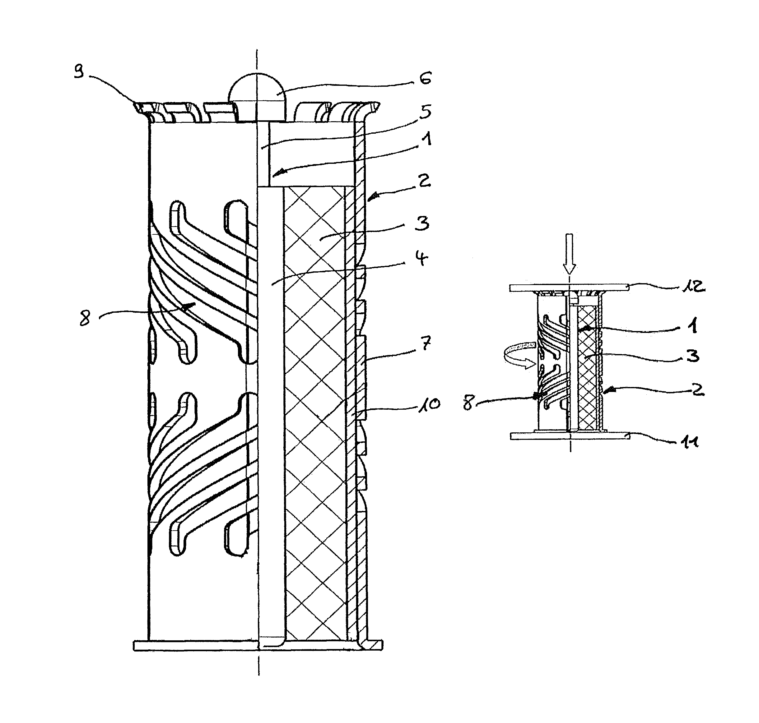
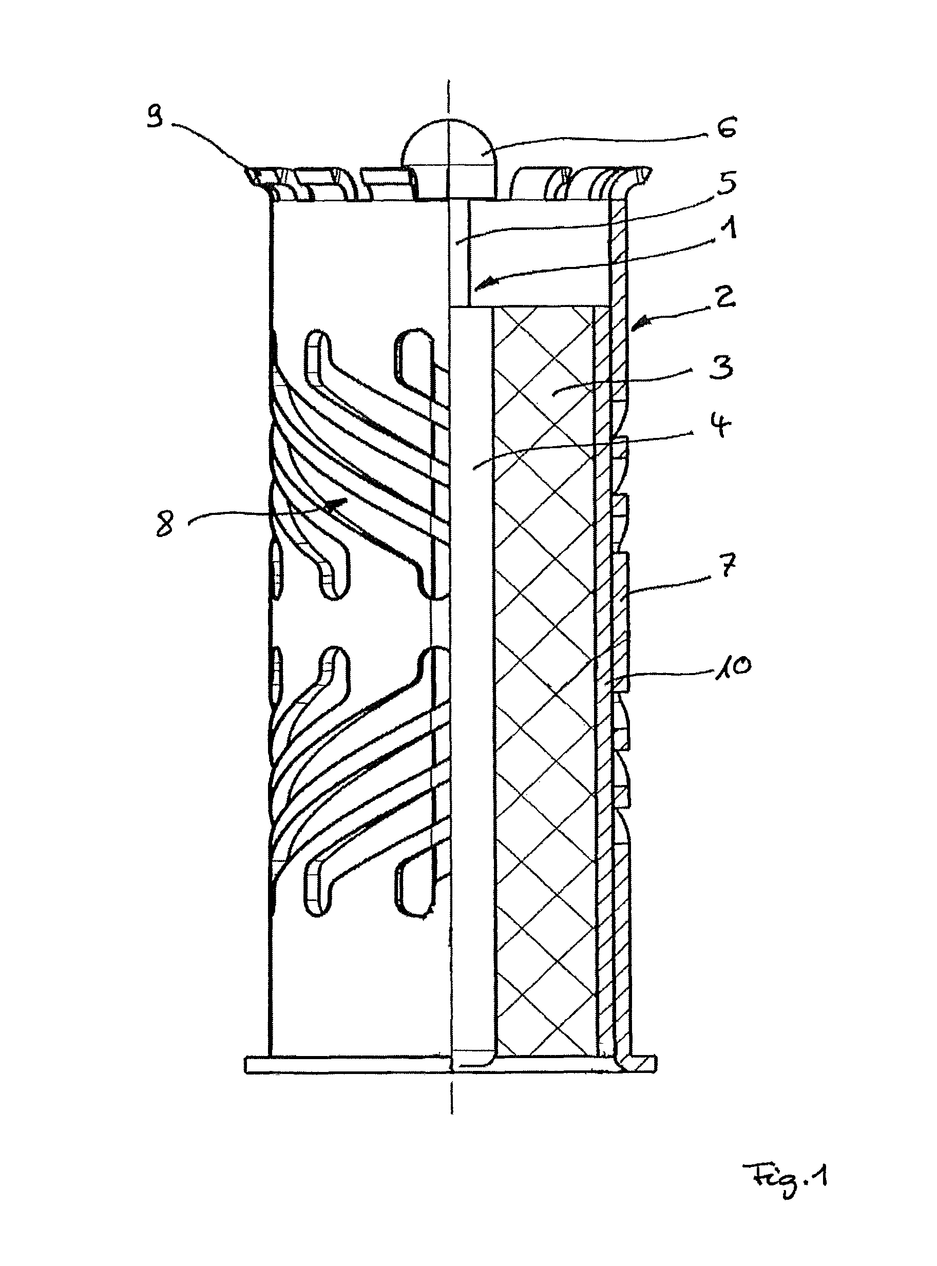
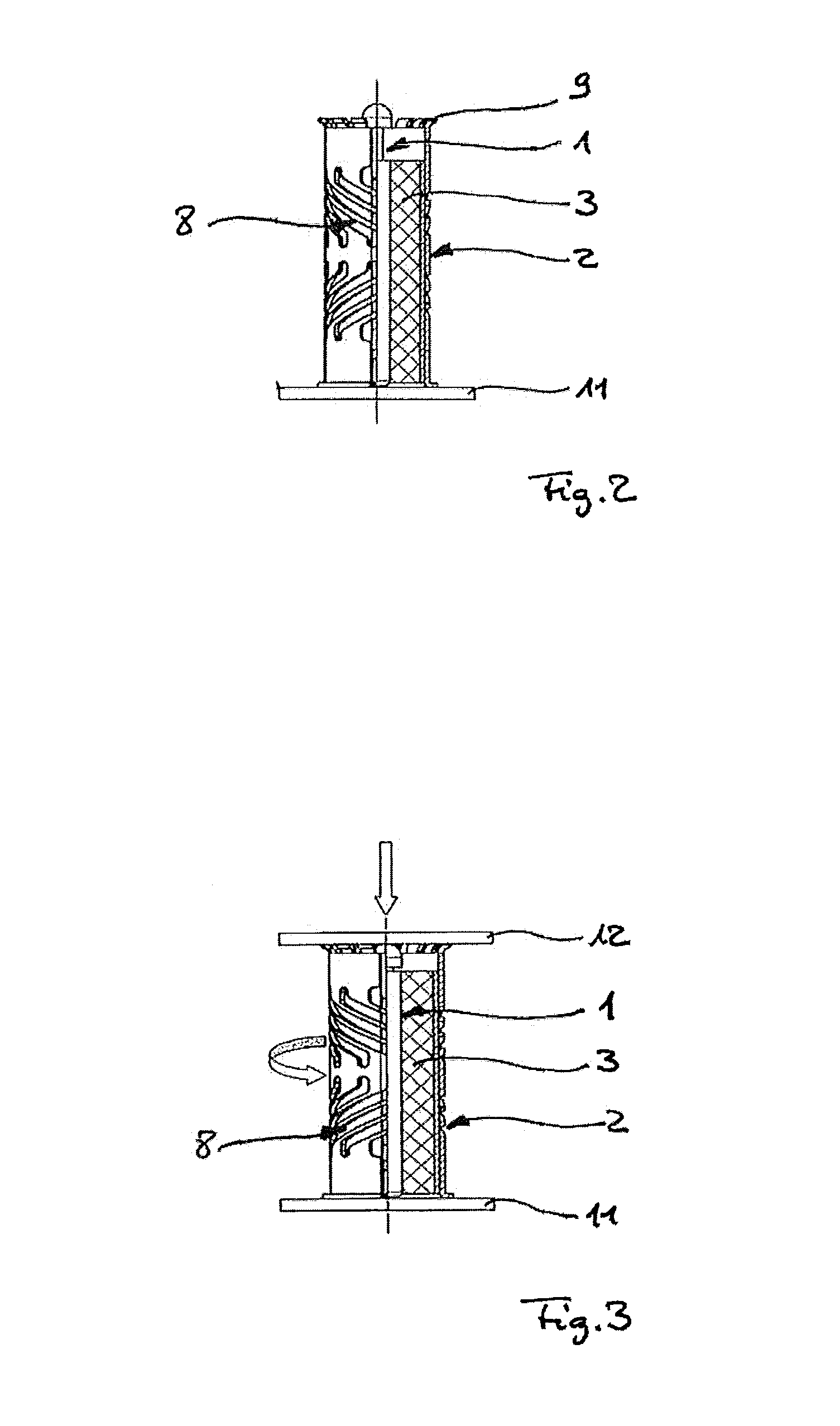
[0021]In describing the preferred embodiment of the present invention, reference will be made herein to FIGS. 1-3 of the drawings in which like numerals refer to like features of the invention.

[0022]The concept underlying the invention is to make the electrical connection between two components by means of a conductor of the simplest possible, and preferably one-piece, construction, and to bring about a compensation for tolerances on the positions of the two components to be connected by a deformation of this conductor due to its structural design.

[0023]What is used for this purpose in accordance with the invention is a conductor which comprises a tubular shell which has at least one opening to reduce the axial stiffness of the shell. The axial stiffness of the shell is so low in this case that the forces which occur when the two components are fitted cause a deformation of the shell in the axial direction which is required due in particular to tolerances on the positions of these ...


PUM


Abstract

A connecting member for the electrically conductive connection of two components, having a (first) conductor which comprises a tubular shell which has at least one opening to reduce axial stiffness.

Description

BACKGROUND OF THE INVENTION[0001]1. Field of the Invention[0002]The invention relates to a connecting member for the electrically conductive connection of two components, and in particular to a connecting member by which radio-frequency signals can be transmitted between two components, and in particular two printed circuit boards, with the greatest possible freedom from losses.[0003]2. Description of Related Art[0004]In the case of connecting members of this kind, it is necessary for them to ensure that the radio-frequency signals are transmitted with the greatest possible freedom from losses even within a defined range of tolerances on the parallelism of the two printed circuit boards and on the distance between them. Further requirements to be met by such connecting members lie in the areas of inexpensive manufacture and easy assembly. Also, the axial and radial dimensions of the connecting member need to be kept as small as possible.[0005]What are used at the moment are chiefly ...

Claims


Application Information

Patent Timeline
Patent Type & Authority Patents(United States)
IPC IPC(8): H01R12/00H01R12/70H01R12/71H01R12/73H01R13/17H01R12/52H01R4/48H01R24/50H01R103/00
CPCH01R12/7082H01R12/712H01R12/714H01R12/732H01R13/17H01R4/48H01R12/52H01R24/50H01R2103/00H01R12/91H01R12/73
Inventor TATZEL, FRANKSCHIELE, GEORGSCHUTT, HAUKE
Owner ROSENBERGER HOCHFREQUENZTECHNIK GMBH & CO KG
Learn More