
Virtual power plant system and method incorporating renewal energy, storage and scalable value-based optimization

a technology of renewable energy and power plant, applied in the field of energy control and management, can solve the problems of not disclosing the aggregate use of stored power in accordance with 975, and achieve the effects of improving the overall economics, efficient distribution of power, and increasing cost savings

Active Publication Date: 2016-03-29
INTELLIGENT GENERATION
View PDF37 Cites 36 Cited by
  • Summary
  • Abstract
  • Description
  • Claims
  • Application Information

AI Technical Summary

Benefits of technology

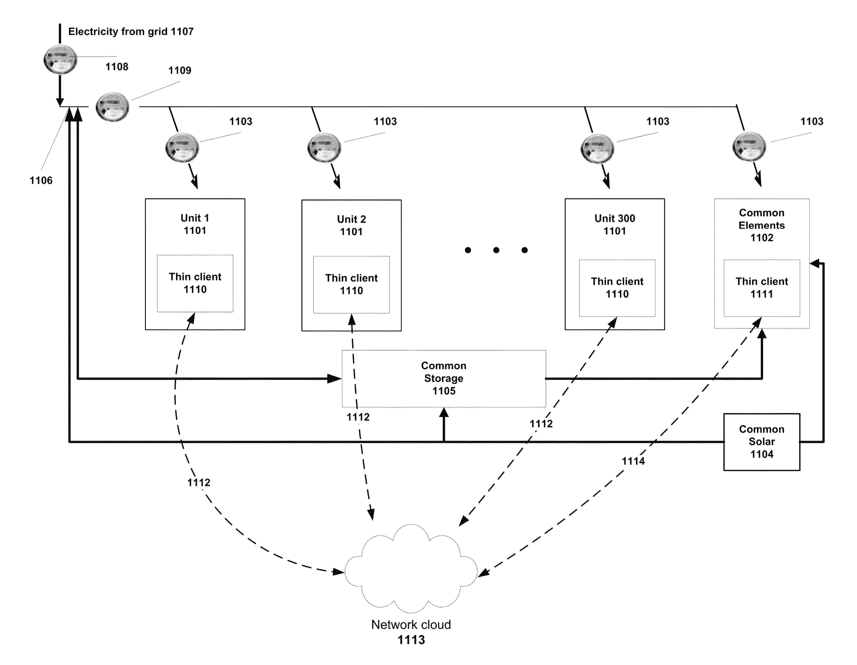
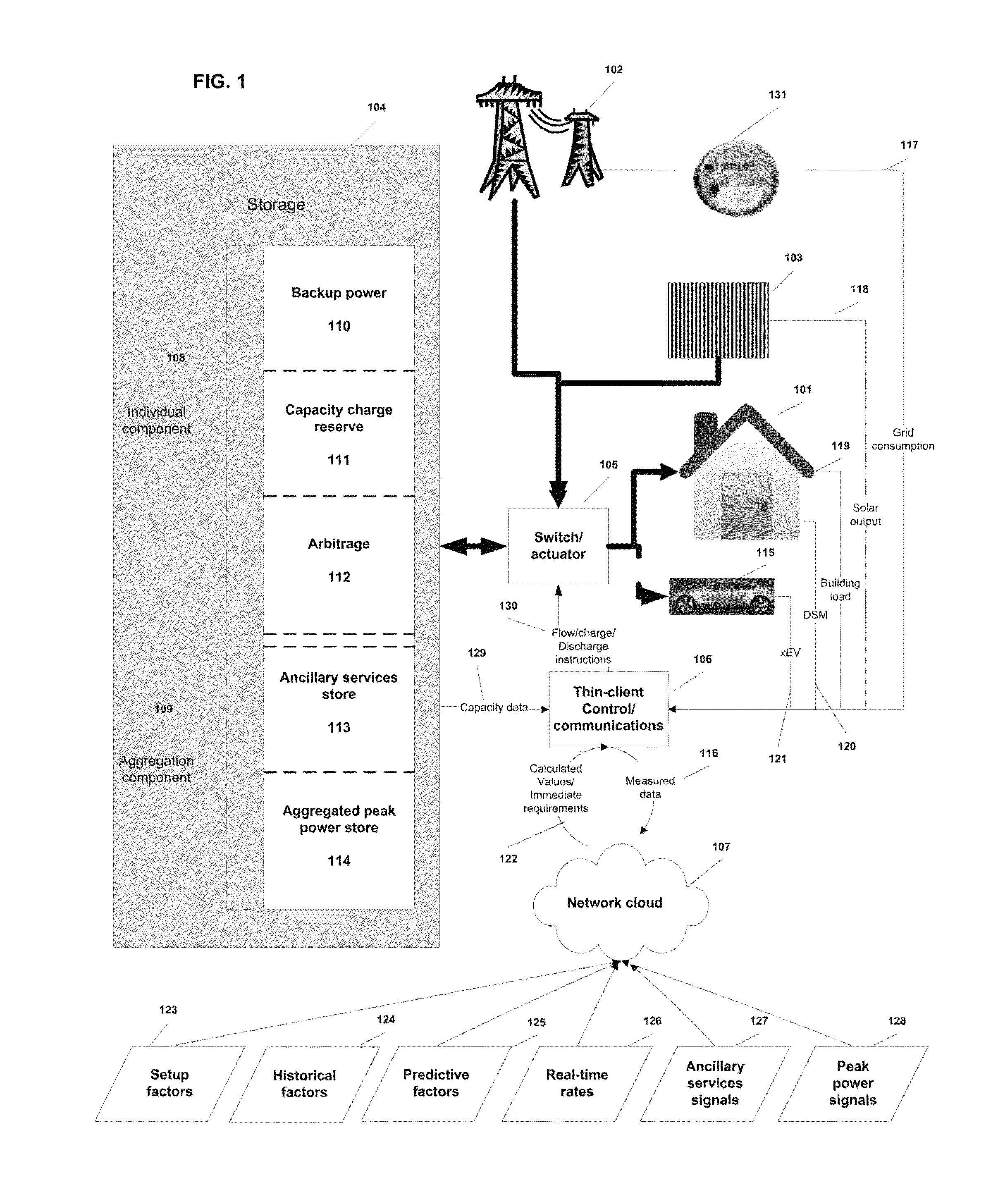
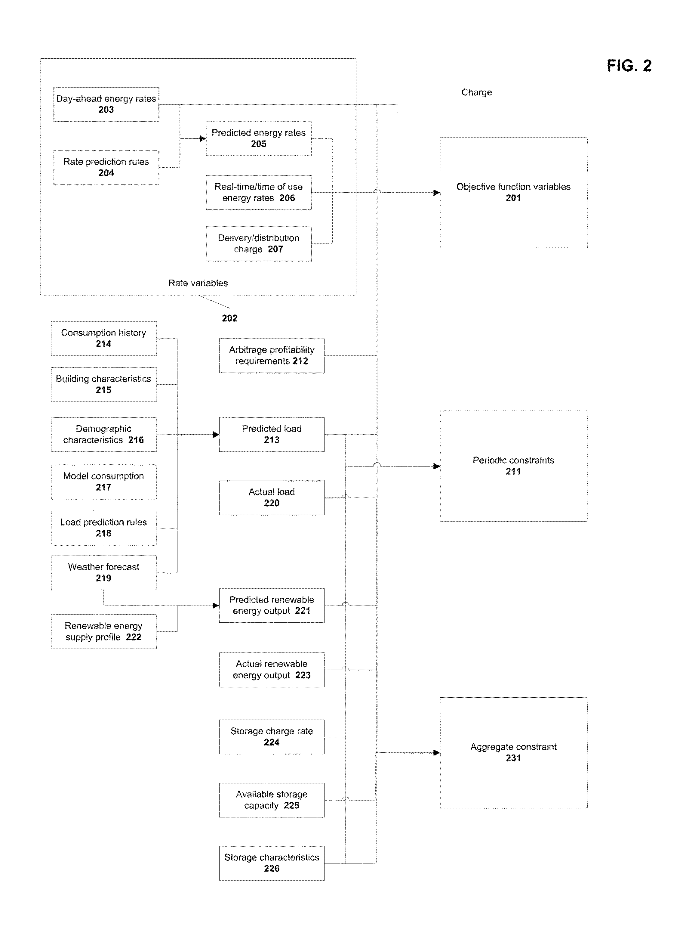
This patent describes a method and system for efficiently distributing power and saving money when renewable energy and energy storage are used in grid-tied buildings. The system takes advantage of the market value of renewable energy and optimizes power distribution using predictive algorithms. It also reduces or eliminates the capacity charge in real-time pricing schemes and provides backup power to the wholesale power markets. The system aggregates data from individual systems to create a virtual power plant, which allows centralized control to respond to pricing signals and accommodate wholesale market requirements. The system takes into account the volatility of wholesale electricity prices and ensures savings from both flat rate and real-time pricing plans. The computer-based algorithms used to optimize cost savings can also be used to determine the optimal amount of renewable energy and storage capacity needed for a given load and real-time rates. Overall, this patent presents a technical solution for achieving cost savings and increased efficiency when using renewable energy and storage in grid-tied buildings.

Problems solved by technology

The '975 patent does not optimize based upon an objective function consisting of current and predicted electricity rates; instead, it shifts load to lower cost times. The '975 also does not disclose the aggregated use of stored power in accordance with a value hierarchy.

Method used


Image

  • Virtual power plant system and method incorporating renewal energy, storage and scalable value-based optimization
  • Virtual power plant system and method incorporating renewal energy, storage and scalable value-based optimization
  • Virtual power plant system and method incorporating renewal energy, storage and scalable value-based optimization

Examples


Embodiment Construction

[0052]While the present disclosure may be susceptible to embodiment in different forms, there are shown in the drawings, and herein will be described in detail, embodiments with the understanding that the present description is to be considered an exemplification of the principles of the disclosure and is not intended to limit the disclosure to the details of construction and the arrangements of components set forth in the following description or illustrated in the drawings.

[0053]Buildings incorporating renewable energy sources like solar and energy storage devices like batteries have four common characteristics. First, they all have demand for electricity, otherwise known as load. Second, their renewable energy sources have the capability to generate some or all of the electricity needed to meet current load requirements if the renewable source is present (e.g., solar power). Third, the storage device has the capability of acquiring electricity when it is free (e.g., when the sola...


PUM


Abstract

Methods and systems provided for creating a scalable building block for a virtual power plant, where individual buildings can incorporate on-site renewable energy assets and energy storage and optimize the acquisition, storage and consumption of energy in accordance with a value hierarchy. Each building block can be aggregated into a virtual power plant, in which centralized control of load shifting in selected buildings, based on predictive factors or price signals, can provide bulk power for ancillary services or peak demand situations. Aggregation can occur at multiple levels, including developments consisting of both individual and common renewable energy and storage assets. The methods used to optimize the system can also be applied to “right size” the amount of renewable energy and storage capacity at each site to maximize return on the capital investment.

Description

CROSS REFERENCE TO RELATED APPLICATIONS[0001]This application claims the benefit of priority under 35 U.S.C. §119(e) to U.S. Provisional Application Ser. No. 61 / 415,002, filed Nov. 18, 2010. The disclosures set forth in the referenced-application is incorporated herein by reference in its entirety.FIELD OF TECHNOLOGY[0002]The present disclosure relates generally to the field of energy control and management, and more particularly, to various computer-based systems and methods for managing the implementation, inclusion and aggregation of distributed renewable energy sources and energy storage in the electric grid in a way that maximizes and optimizes energy distribution, and hence value for the asset owners, aggregators, utilities and regional transmission organizations (RTOs).BACKGROUND[0003]A fundamental challenge of the current electricity infrastructure is incorporating renewable energy sources into the existing grid to make it cheaper, cleaner, more efficient and more reliable. ...

Claims


Application Information

Patent Timeline
Patent Type & Authority Patents(United States)
IPC IPC(8): G06F1/28H02J3/38H02J3/32G06Q10/04G06Q50/06H02J3/14
CPCH02J3/386G06Q10/04G06Q50/06H02J3/32H02J3/383Y02E10/563Y02E10/566H02J2003/146Y02B10/14Y02E10/763Y02E70/30Y04S50/00H02J2310/64H02J2310/48H02J3/322H02J2300/28H02J2300/24H02J3/381H02J3/14Y02B10/10Y02E10/56Y02E10/76Y02T90/167Y04S30/14Y04S20/222Y02B70/3225H02J3/40Y04S50/16G05B15/02
Inventor MARHOEFER, JOHN, J.
Owner INTELLIGENT GENERATION
Learn More