Anti-flicker apparatus for motion detector

a motion detector and anti-flicker technology, applied in lighting devices, electrical devices, light sources, etc., can solve the problems of ccfls flickering, leds emitted soft glow, fluorescent light bulbs not being available in the united states, etc., and achieves higher voltage and higher voltage

Active Publication Date: 2016-03-29
HASLER GREGORY S
View PDF6 Cites 0 Cited by
  • Summary
  • Abstract
  • Description
  • Claims
  • Application Information

AI Technical Summary

Benefits of technology

[0010]In order to achieve these goals, an aspect of the present invention is to provide an inexpensive and energy efficient apparatus that can be easily installed by consumers between a light socket and an energy efficiency lighting element for light sockets controlled by commonly powered electronic switching devices to prevent flickering and glowing of the energy efficient lighting element during the off state.
[0012]A first embodiment of the present invention includes a switchable light source, a switchable load, a controller, and a voltage sensor. A second embodiment of the present invention includes a switchable load, a controller, a local power supply, and a voltage sensor. Both embodiments of the present invention are designed to provide a minimal load for the minor current to pass through in the “off” state. When the present invention in the first embodiment detects a higher current passing through the minimal load, and therefore a higher voltage, thus indicating the lamp has been switched from the “off” state to the on state, the switchable load is disconnected, and the current is re-routed to pass through the energy efficient lamp. Thus, no power is wasted passing current through the switchable load in the “on” state. In the second embodiment, when the present invention detects a higher current passing through the minimal load, and therefore a higher voltage, thus indicating the lamp has been switched from the “off” state to the on state, current through the switchable load is turned off, and the power current is directed to pass through the energy efficient lamp. In the second embodiment, the load resistor is used to hold the voltage low across the hot and neutral line, thus keeping the CCFL from firing.

Problems solved by technology

Within the next few years incandescent light bulbs are not expected to be available in the marketplace of the United States.
For instance, it has been discovered that fluorescent light bulbs do not function properly when connected to commonly powered electronic switching devices such as motion detectors, electronic timers, and other devices requiring a low current to pass through the lighting element to provide power to the electronic switching device while the lighting element is in the “off” state.
This is typically required due to the wiring limitations of residential homes and other building structures, wherein a small current is required to pass through the lighting element in order to provide current to the electronic switching device.
The filament used in incandescent light bulbs allows small currents to pass through the incandescent light bulbs without lighting the bulb because the small current does not experience enough resistance to cause the filament to heat up and glow or light.
High efficiency lighting element, however, such as CCFLs and Light Emitting Diodes (LEDs) are very sensitive to low currents, thus causing LEDs to emit a soft glow and CCFLs to flicker when a low current passes through theses lighting elements.
Low currents cause the ballasts in CCFLs to false start which results in the lamp flickering on and off.
This flickering can become quite bothersome and annoying to individuals in the area.
Furthermore, the flickering is damaging to the overall life of the CCFL.

Method used


Image

  • Anti-flicker apparatus for motion detector
  • Anti-flicker apparatus for motion detector
  • Anti-flicker apparatus for motion detector

Examples


first embodiment

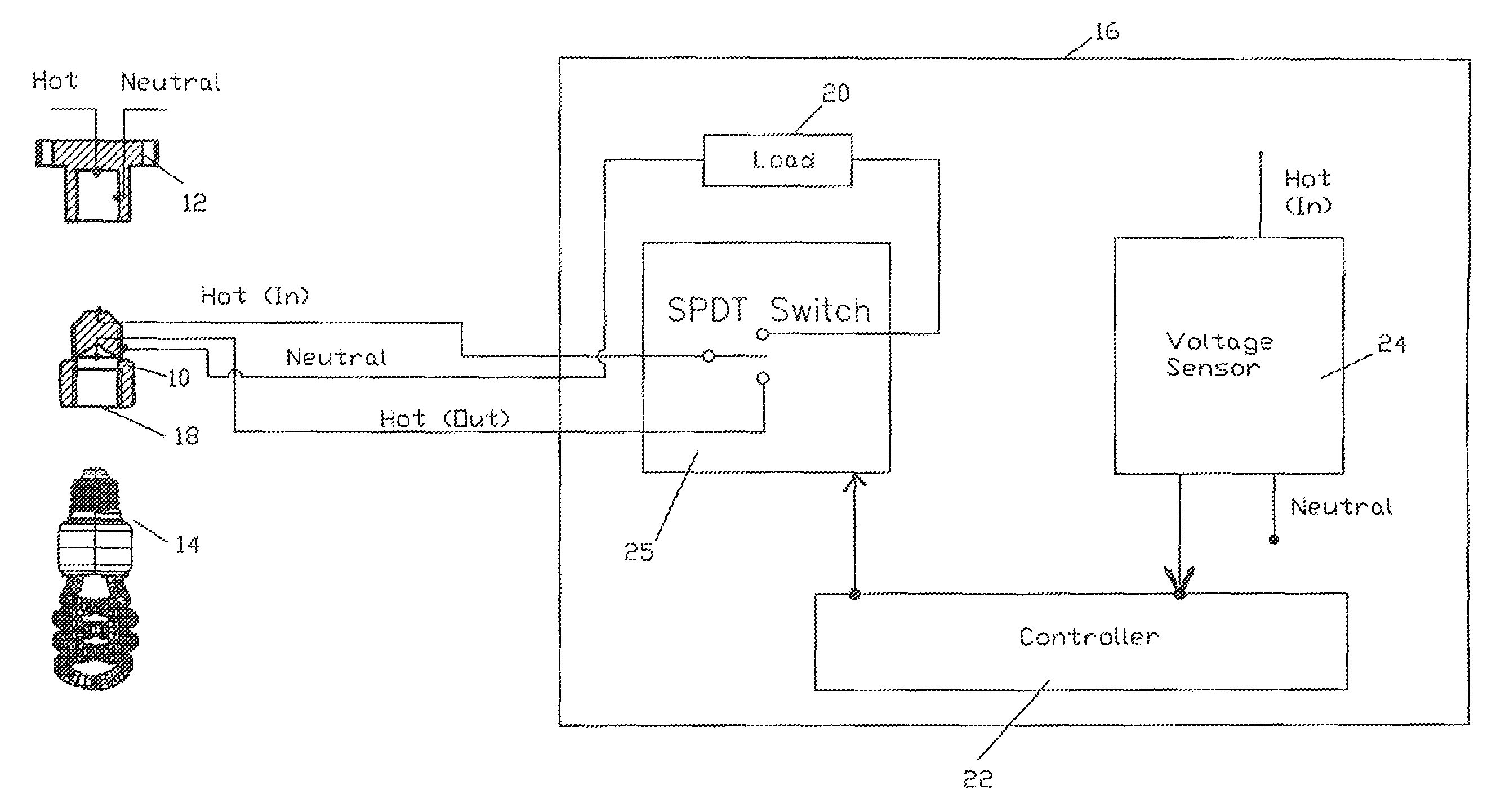
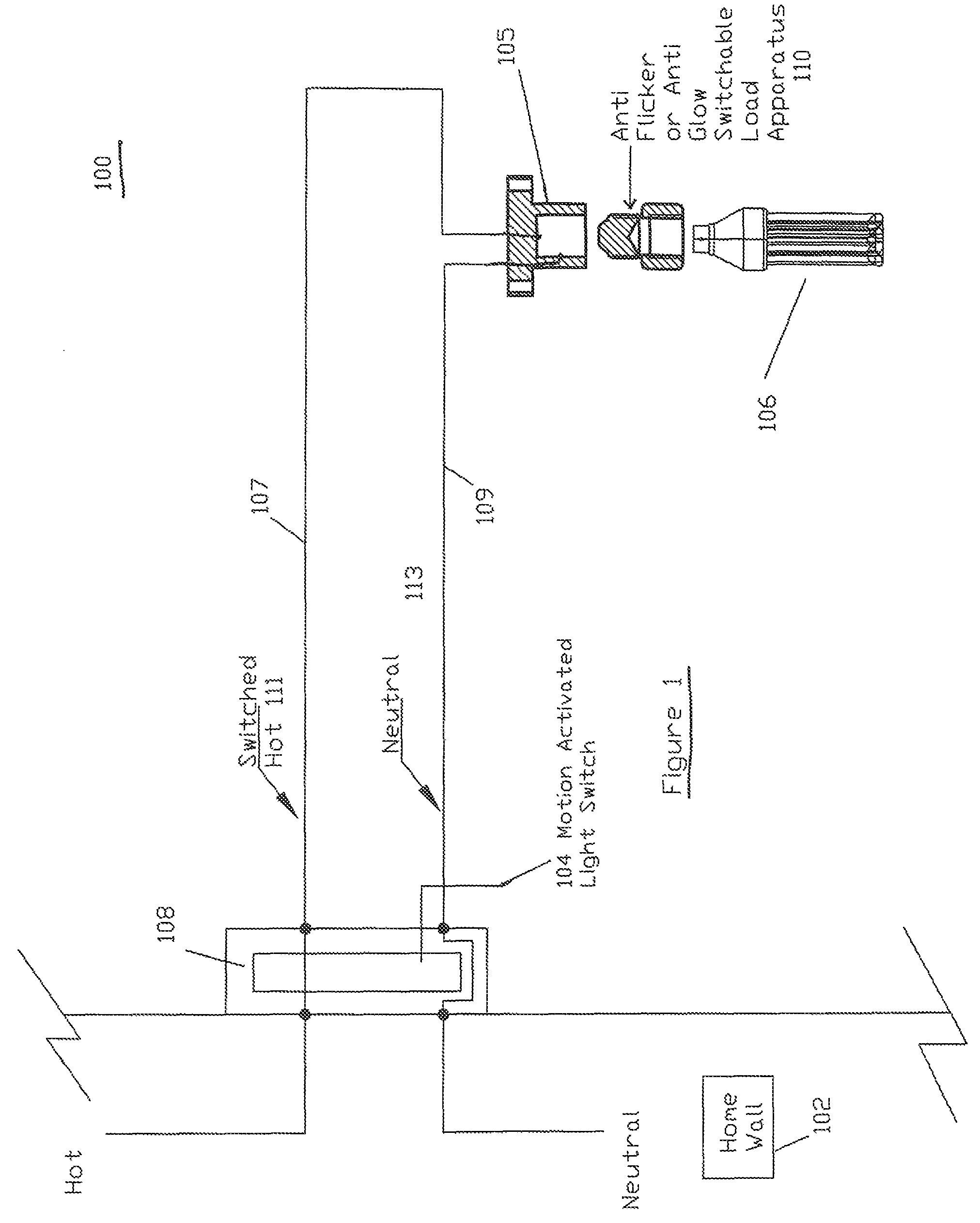
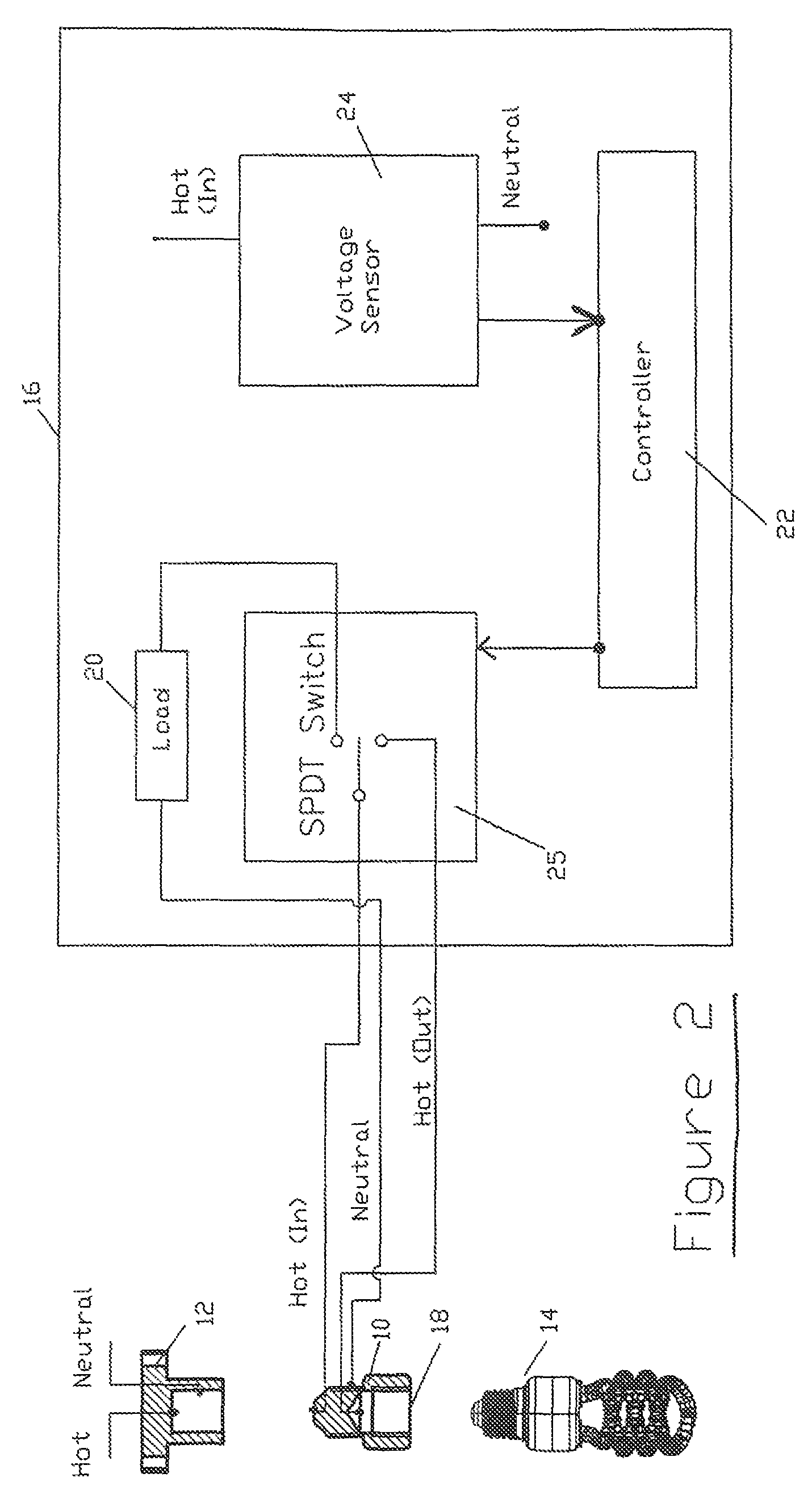
[0020]FIG. 2 illustrates a block diagram of anti-flicker or anti-glow apparatus 10 configured in accordance with the present invention. The apparatus 10 preferably is configured to be easily screwed into the original socket 12 of an electronically activated light source, such as an internal wall-mounted motion activated light switch using an energy efficient lamp 14, such as a CCFL or a CFL. The energy efficient lamp is simply screwed into the light socket 18 of the anti-flicker apparatus 10.

[0021]Block diagram 16 illustrates the internal electrical components of the anti-flicker apparatus 10 configured in accordance with a first embodiment of the present invention. Included in the anti-flicker apparatus 10 are a switchable load 20, a controller 22, a voltage sensor 24, and a switchable light source 23. In the illustrated embodiment, the switchable light source 25 is a Single-Pull Double-Through (SPDT) switch. The anti-flicker apparatus 10 is electrically connected between the light...

second embodiment

[0024]FIG. 4 is a block diagram of an anti-flicker or anti-glow switchable load apparatus 50 configured in accordance with the present invention. Illustrated is a motion detector 52 including a light socket 54 that is activated by the motion detector. The motion detector security light 52 is designed to be electrically connected and mounted to an electrical switch box for a light fixture having a “hot” wire connection 53 and a “neutral” wire connection 55. The components of the anti-flicker switchable load apparatus 50 are illustrated in the block diagram 60 shown in FIG. 4. The anti-flicker switchable load apparatus 50 includes a socket 58 for receiving an energy efficient lamp 56.

[0025]The block diagram 60 of the anti-flicker switchable load apparatus 50 include a switchable load 62, a controller and local power supply 64, and a voltage sensor 66. Similar to the first embodiment, the switchable load 62 provides a path for the small current providing power to the motion detector du...


PUM


Abstract

An anti-flicker and anti-glow switchable load apparatus to be installed in the light socket of a commonly powered electronic switching device, such as a motion activated light switch. An energy efficient light bulb or lamp, such as a cathode fluorescent lamp or light emitting diode is then screwed into the apparatus. A first embodiment of the present invention includes a switchable light source, a switchable load, a controller, and a voltage sensor. When the present invention in the first embodiment detects a higher voltage, thus indicating the lamp has been switched from the “off” state to the on state, the switchable load is disconnected, and the current is re-routed to pass through the energy efficient lamp.

Description

REFERENCE TO RELATED APPLICATION[0001]This patent application claims priority to U.S. provisional patent application entitled “CFL Anti Flicker Device,” having Ser. No. 61 / 562,425 filed on Nov. 21, 2011, the entirety of which is hereby incorporated by reference into the present patent application.BACKGROUND OF THE INVENTION[0002]1. Field of the Invention[0003]The present invention relates generally to lighting circuitry, and more particularly, to lighting circuitry for stabilizing operation of a high efficiency lighting element activated by an automated switching apparatus, such as a light switch motion detector.[0004]2. Description of Related Art[0005]Higher efficiency lighting elements, such as Cold Cathode Fluorescent Lamp (CCFL), are becoming extremely popular due to the current “Green” movement. Current government mandates are requiring incandescent bulbs to be phased out of production in favor high efficiency fluorescent light bulbs, such as CCFLs and Light Emitting Diodes (LE...

Claims


Application Information

Patent Timeline
Patent Type & Authority Patents(United States)
IPC IPC(8): H05B37/00H05B37/02
CPCH05B37/0227H05B37/02Y02B20/44H05B47/10H05B47/115Y02B20/40
Inventor HASLER, GREGORY, SCOTTTUTT, TIMOTHY, THOMAS
Owner HASLER GREGORY S
Why Eureka
Try Eureka