
Electric fastening head for fastening lock nut of single through shaft

a technology of electric tightening and lock nuts, which is applied in the direction of wrenches, screwdrivers, metal-working devices, etc., can solve the problems of low efficiency, inability to meet the torque requirements of the assembly process, and difficult operation, so as to improve production efficiency, high tightening precision, and simple and convenient operation

Active Publication Date: 2016-04-05
DALIAN DEXIN M&E TECH ENG
View PDF6 Cites 0 Cited by
  • Summary
  • Abstract
  • Description
  • Claims
  • Application Information

AI Technical Summary

Benefits of technology

The purpose of this invention is to provide an electric tightening head for tightening a lock nut of a single through shaft that is easy to operate and achieves high levels of tightening accuracy. The benefits include simple and convenient operation, improved production efficiency, and reduced labor costs. Additionally, the invention solves the problem of difficulty in ensuring assembly technical requirements and wastes time and labor due to structural particularity of the work piece when field mounting the lock nut.

Problems solved by technology

In a case where the through shaft is being mounted to axle housing, since a lock nut has already been fitted on the shaft, operations become difficult due to the narrow space.
As a result, a specially hook-shaped wrench has to be is used to tighten the nut little by little, which leads to low efficiency, and the torque requirement of the assembly process cannot be met.
Finally, it is still necessary to realize locking by means of punching and riveting, which makes the assembly requirement of high-quality driving axle hard to be met.

Method used


Image

  • Electric fastening head for fastening lock nut of single through shaft
  • Electric fastening head for fastening lock nut of single through shaft

Examples


Embodiment Construction

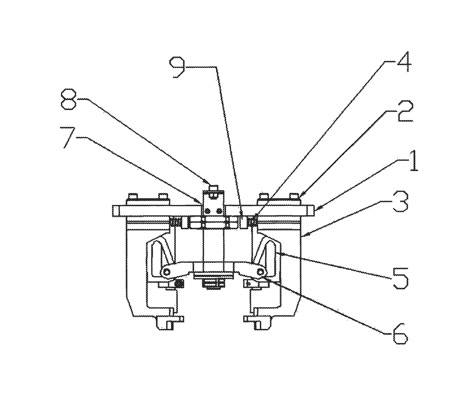
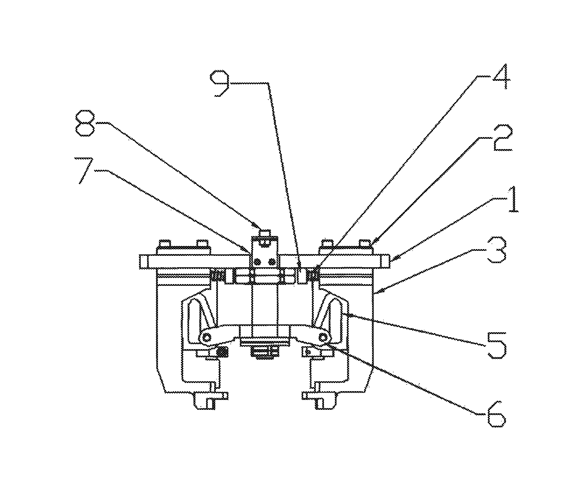
[0008]The reference numbers in FIG. 1 are as follows: supporting plate 1, sliding block 2, tightening jaw 3, spring 4, wedged pad iron 5, wedged pad iron connecting arm 6, pulling rod 7, initial position detecting bolt 8, and stop bolt 9.

[0009]An electric tightening head for tightening a lock nut of a single through shaft, as shown in FIG. 1, is mainly structured as follows: the supporting plate 1 is connected with the sliding blocks 2, the tightening jaws 3 and the pulling rod 7; the springs 4 are connected with the stop bolts 9 mounted on the tightening jaws 3; the tightening jaws 3 are connected with the wedged pad irons 5; the wedged pad irons 5 are connected with the wedged pad iron connecting arms 6; and an upper end of the pulling rod 7 is connected with the initial position detecting bolt 8.

[0010]The present invention is connected with a suspended electric tightening machine. Before the tightening machine starts to work, the tightening jaws 3 of the lock nut of the single th...


PUM


Abstract

An electric tightening head for tightening a lock nut of a single through shaft, comprising a supporting plate (1), sliding blocks (2), tightening jaws (3), springs (4), wedged pad irons (5), wedged pad iron connecting arms (6), a pulling rod (7), an initial position detecting bolt (8) and stop bolts (9), wherein the supporting plate (1) is connected with the sliding blocks (2), the tightening jaws (3) and the pulling rod (7); the springs (4) are connected with the stop bolts (9) mounted on the tightening jaws (3); the tightening jaws (3) are connected with the wedged pad irons (5); the wedged pad irons (5) are connected with the wedged pad iron connecting arms (6); and an upper end of the pulling rod (7) is connected with the initial position detecting bolt (8).

Description

TECHNICAL FIELD[0001]The present invention relates to an electric tightening machine field, particularly to an electric tightening head for tightening a lock nut of a single through shaft.BACKGROUND[0002]A flange portion of a common through shaft is integrated with the shaft. In a case where the through shaft is being mounted to axle housing, since a lock nut has already been fitted on the shaft, operations become difficult due to the narrow space. As a result, a specially hook-shaped wrench has to be is used to tighten the nut little by little, which leads to low efficiency, and the torque requirement of the assembly process cannot be met. Finally, it is still necessary to realize locking by means of punching and riveting, which makes the assembly requirement of high-quality driving axle hard to be met.SUMMARY OF THE INVENTION[0003]In view of the disadvantages in the prior art, the purpose of the present invention is to provide an electric tightening head for tightening a lock nut ...

Claims


Application Information

Patent Timeline
Patent Type & Authority Patents(United States)
IPC IPC(8): B25B13/02B23P19/06
CPCB23P19/06B25B13/02
Inventor QI, ZHAOJUNHUANG, YUEJIN
Owner DALIAN DEXIN M&E TECH ENG
Learn More