Check patentability & draft patents in minutes with Patsnap Eureka AI!

Resistance memory cell

a memory cell and resistance technology, applied in the field of resistance memory cells, can solve the problems of difficult or impossible to determine whether the measured read current is measured, the value of stored data is difficult to determine, and the use of an access device alters the current-voltage behavior

Active Publication Date: 2016-04-05
HEFEI RELIANCE MEMORY LTD
View PDF34 Cites 17 Cited by
  • Summary
  • Abstract
  • Description
  • Claims
  • Application Information

AI Technical Summary

Benefits of technology

The patent text describes a type of memory technology called resistance change memory, which uses resistance change materials to store data. These memories have the advantage of being low-cost and high-density. The technology uses a conductive-bridging resistance-change memory element that can switch between a low-resistance state and a high-resistance state by applying voltage pulses of different polarities. The resistance change is achieved by applying a positive voltage pulse of a SET threshold voltage to the resistance memory element, which causes the resistance to drop by several orders of magnitude. The resistance memory element can also be read by measuring the read current that flows through it. However, there are challenges in detecting the resistance state of the resistance memory element accurately due to the influence of parasitic currents. To address this problem, access devices are used to select the resistance memory element to be read, but this alters the current-voltage behavior of the resistance memory cell. The patent text also describes the physical structures of the resistance memory cells and the challenges in accurately detecting the resistance state.

Problems solved by technology

Such parasitic currents can make it difficult or impossible to determine whether the measured read current represents the high-resistance state or the low-resistance state of the resistance memory element that was selected to be read.
Since the read current is used to determine the data value stored in the resistance memory element, it is consequently difficult to determine the value of the stored data.
However, the use of an access device alters the current-voltage behavior of a resistance memory cell that incorporates a resistance memory element and an access device.

Method used


Image

  • Resistance memory cell
  • Resistance memory cell
  • Resistance memory cell

Examples


Embodiment Construction

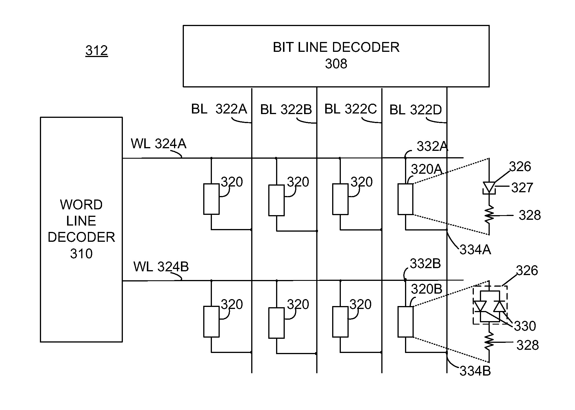
[0015]A number of different memory technologies are based on resistance change. Magneto resistance random access memories utilize a magnetic field to affect the resistance change. Phase-change random access memories utilize thermal processes to control a phase transition in a resistance change material. The phase transition is from an amorphous to a crystalline state. A conductive-bridging resistance-change random access memory (“CB-RAM”) is a type of resistance change memory technology that is based on the electrically-stimulated change of the resistance of a metal-insulator-metal resistance memory cell.

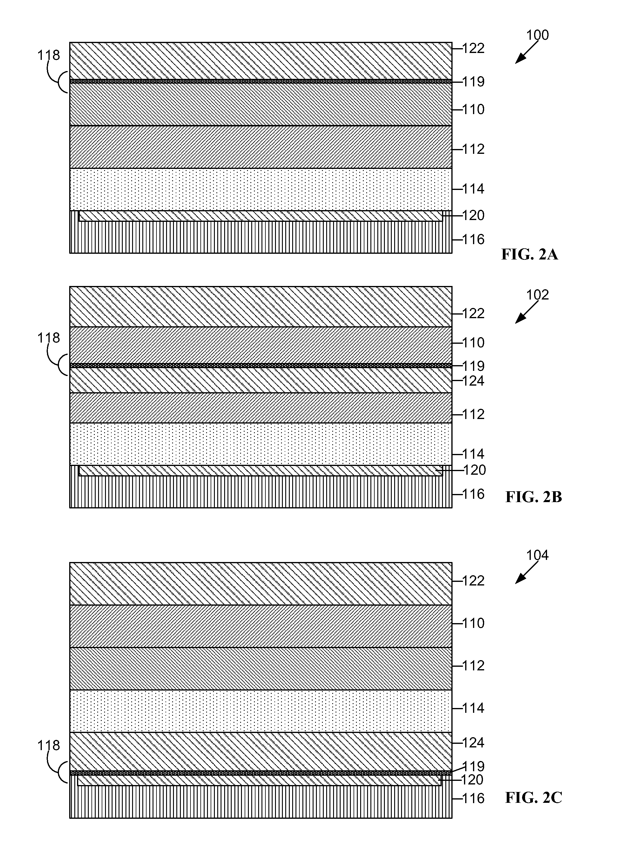
[0016]CB-RAM memory elements based on solid electrolytes, sometimes known as programmable metallization elements, are of particular interest due to the ability of low voltages to change their resistance states and their potential for high scalability. Typically, CB-RAM memory elements, which are referred to herein as resistance memory elements have a dielectric material disposed bet...


PUM


Abstract

A resistance memory includes a resistance memory cell having a resistance memory element and a two-terminal access device in series. The two-terminal access device affects the current-voltage characteristic of the resistance memory cell. The resistance memory additionally includes a circuit to apply across the resistance memory cell a set pulse having a set polarity to set the resistance memory cell to a low-resistance state that is retained after application of the set pulse, a reset pulse having a reset polarity, opposite to the set polarity, to reset the resistance memory cell to a high-resistance state that is retained after application of the reset pulse, and a read pulse of the reset polarity and smaller in magnitude than the reset pulse to determine the resistance state of the resistance memory cell without changing the resistance state of the resistance memory cell.

Description

BACKGROUND[0001]A conductive-bridging resistance-change memory element, which will be referred to herein as a resistance memory element, has at least two distinct stable resistance states: a low-resistance state and a high-resistance state. A resistance memory element can be switched from a high-resistance state to a low-resistance state by the application of a voltage pulse of one polarity and can be switched from a low-resistance state to a high-resistance state by the application of a voltage pulse of the opposite polarity. Each resistance state is used to represent a respective data value, e.g., 1 or 0. Since the resistance changes can be accomplished by applying low-voltage pulses to the resistance memory element, and the resistance state of the resistance memory element can be determined by applying a voltage or a current to the resistance memory element, resistance memory elements are attractive for use in low-cost, high-density memory arrays.[0002]FIG. 1 depicts the basic cu...

Claims


Application Information

Patent Timeline
Patent Type & Authority Patents(United States)
IPC IPC(8): G11C13/00H01L45/00H01L27/24
CPCG11C13/004G11C13/00G11C13/003G11C13/0011G11C13/0069H01L27/2409H01L27/2418H01L45/085H01L45/1233H01L45/142H01L45/143G11C2013/0073G11C2013/0083G11C2213/72H10B63/22H10B63/20H10N70/245H10N70/8822H10N70/8825H10N70/826G11C13/0097G11C2013/0052
Inventor KELLAM, MARK D.BRONNER, GARY BELA
Owner HEFEI RELIANCE MEMORY LTD
Features
  • R&D
  • Intellectual Property
  • Life Sciences
  • Materials
  • Tech Scout
  • Unparalleled Data Quality
  • Higher Quality Content
  • 60% Fewer Hallucinations
Learn More