Connection method between braided shield layer of shiled wire and drain wire, and connection structure of the same

a technology of drain wire and shield layer, which is applied in the direction of connection contact material, connection details of line/current collector, and connection effected by permanent deformation, etc., can solve the problems of shield performance reduction and reliability reduction, and achieve easy and reliable connection, reliable connection, and easy to judge with eyes

Active Publication Date: 2016-04-05
YAZAKI CORP
View PDF8 Cites 6 Cited by
  • Summary
  • Abstract
  • Description
  • Claims
  • Application Information

AI Technical Summary

Benefits of technology

[0018]According to the connection method between a braided shield layer of a shield wire and a drain wire of the present invention, an easy and reliable connection is available. Further, because a concave is finally formed on the shield ring, an end of the process can be extremely easily judged with eyes.
[0019]According to the connection structure between a braided shield layer of a shield. wire and a drain wire of the present invention, a reliable connection is available. Further, because a concave is finally formed on the shield ring, an end of the process can be extremely easily judged with eyes.

Problems solved by technology

Therefore, there is a problem that reliability is reduced, and an operator must be skilled in soldering.
As a result, there is a problem that the shield performance is reduced.

Method used


Image

  • Connection method between braided shield layer of shiled wire and drain wire, and connection structure of the same
  • Connection method between braided shield layer of shiled wire and drain wire, and connection structure of the same
  • Connection method between braided shield layer of shiled wire and drain wire, and connection structure of the same

Examples


Embodiment Construction

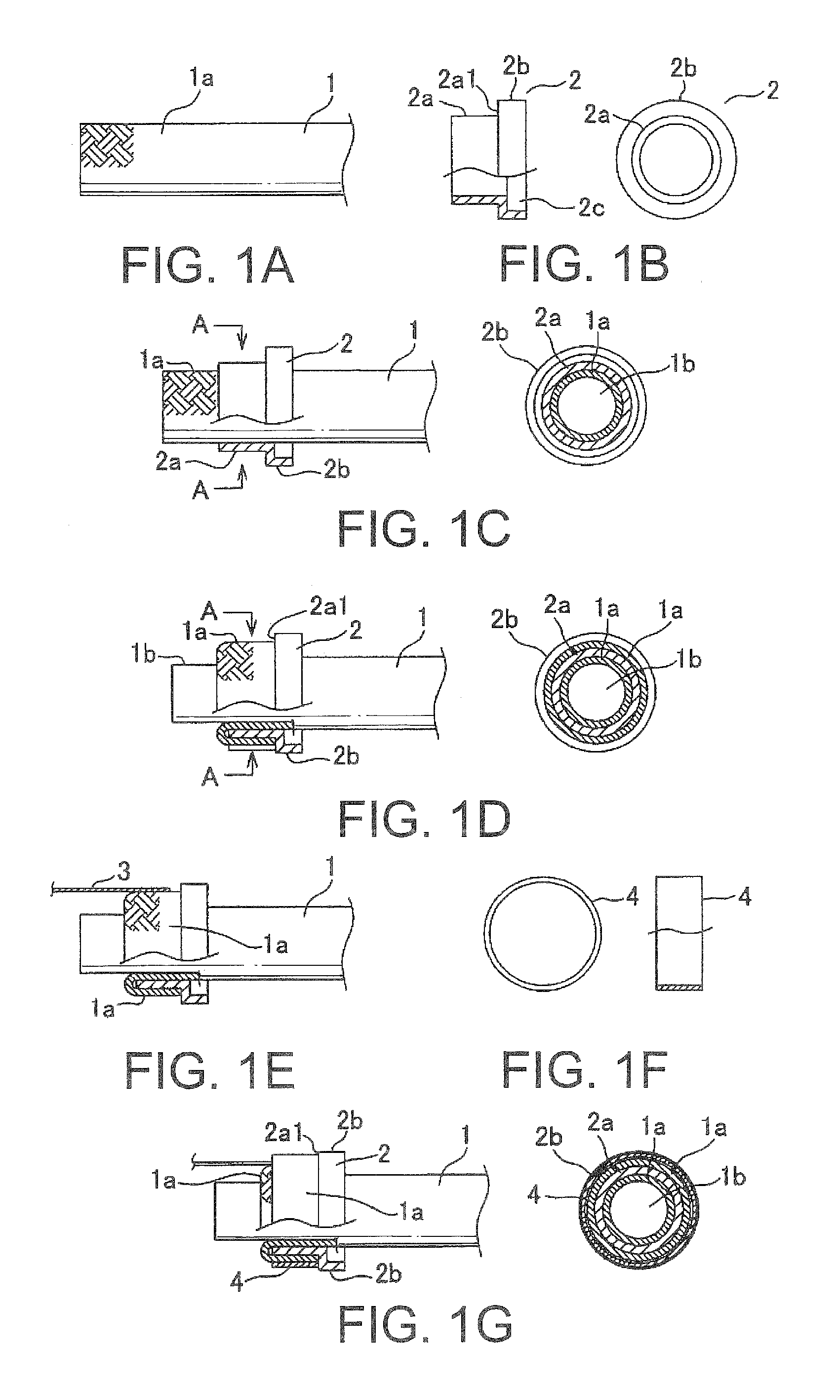
[0038]A connection method between a braided shield layer of a shield wire and a drain wire according to the present invention will be explained with reference to figures.

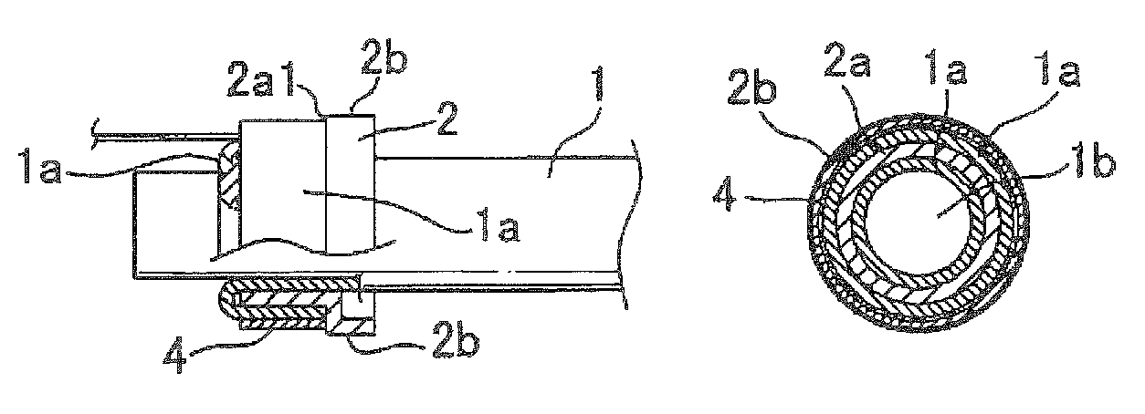
[0039]FIG. 1A schematically shows a vicinity of an end of a braided shield layer 1a of a shield wire 1 to be connected to a drain wire 3.

[0040]In this embodiment, the braided shield layer 1a provided as a most outer layer of the shield wire 1 is formed by braiding a plurality of conductive wire bundles each composed of a plurality of (eighty in this embodiment) conductive element wires thinner than (outer diameter is 0.24 millimeters, made of metal plated fibers in this embodiment) later-described element wires of the drain wire.

[0041]A shield terminal 2 as schematically shown in a side view and a front view of FIG. 1B is inserted over from an end of the shield wire 1 (FIG. 1C shows a schematic side view and a schematic sectional view of line A-A). The maneuvering gear 2 is composed of a ring portion 2a and an enlar...


PUM

PropertyMeasurementUnit
outer diameteraaaaaaaaaa
radiusaaaaaaaaaa

Abstract

[Technical Problem]To provide a connection method between a braided shield layer of a shield wire and a drain wire, and a connection structure of the same enabling an easy and reliable connection, using no skilled operation such as soldering, and without an increase of non-shield area which is a problem when the braided shield layer is pulled out and a ground terminal is directly crimped onto the braided shield layer.[Solution to Problem]A connection method between a braided shield layer of a shield wire and a drain wire sequentially including the steps of a shield terminal insertion step; a shield layer folding and overlapping step; a drain wire overlapping step; a shield ring inserting step; and a crimping step.

Description

TECHNICAL FIELD[0001]This invention relates to a connection method between a braided shield layer of a shield wire used for connecting with electric components such as a motor used in an electric vehicle or the like, and a drain wire for a ground connection.BACK GROUND ART[0002]A shield wire provided with a braided shield layer as the most outer layer formed by braiding a plurality of conductive wire bundles each composed of a plurality of conductive element wires is used for preventing an electromagnetic wave from leaking from a conductor to an outside, or for removing an influence of an electromagnetic wave to the conductor from the outside.[0003]In these shield wires, normally the braided shield layer is electrically connected to ground for attaining a shield effect. For this purpose, a grounding wire, namely, a drain wire 3 and a braided shield layer 1a are electrically connected to each other as shown in FIG. 3. In an example of FIG. 3, they are connected by soldering (referenc...

Claims


Application Information

Patent Timeline
Patent Type & Authority Patents(United States)
IPC IPC(8): H05K9/00H01R43/048H01R4/20H01R4/66H01R9/05H01B5/12
CPCH01R43/048H01B5/12H01R4/20H01R4/66H01R9/0512H01R9/0518H05K9/0088H05K9/0098Y10T29/49199
Inventor HANAZAKI, HISASHI
Owner YAZAKI CORP
Why Eureka
Try Eureka