Supercharge Your Innovation With Domain-Expert AI Agents!

High voltage maximum voltage selector circuit with no quiescent current

a selector circuit and high voltage technology, applied in the field of circuits, can solve the problems of imposing a continuous load burden, requiring complex and costly circuitry,

Active Publication Date: 2016-04-05
ANALOG DEVICES INT UNLTD
View PDF7 Cites 7 Cited by
  • Summary
  • Abstract
  • Description
  • Claims
  • Application Information

AI Technical Summary

Benefits of technology

The patent describes a circuit that selects the highest voltage input from multiple inputs without drawing current from any of the inputs. It consists of a voltage selection circuit that automatically selects the input with the highest voltage magnitude, delivers it to the output, and uses FETs to prevent damage to the circuit components. The circuit does not draw any current from the output and can have any number of inputs. The technical effect of this circuit is to provide a reliable and efficient way to select the highest input voltage from multiple inputs without causing damage or current leakage.

Problems solved by technology

This could impose a continuous load burden, which could be a problem for applications that rely on a battery for operation.
However, these techniques may require bias current in amplifiers to generate the maximum voltages.
In addition, these techniques may require complex and costly circuitry.

Method used


Image

  • High voltage maximum voltage selector circuit with no quiescent current
  • High voltage maximum voltage selector circuit with no quiescent current
  • High voltage maximum voltage selector circuit with no quiescent current

Examples


Embodiment Construction

[0024]Illustrative embodiments are now described. Other embodiments may be used in addition or instead. Details that may be apparent or unnecessary may be omitted to save space or for a more effective presentation. Some embodiments may be practiced with additional components or steps and / or without all of the components or steps that are described.

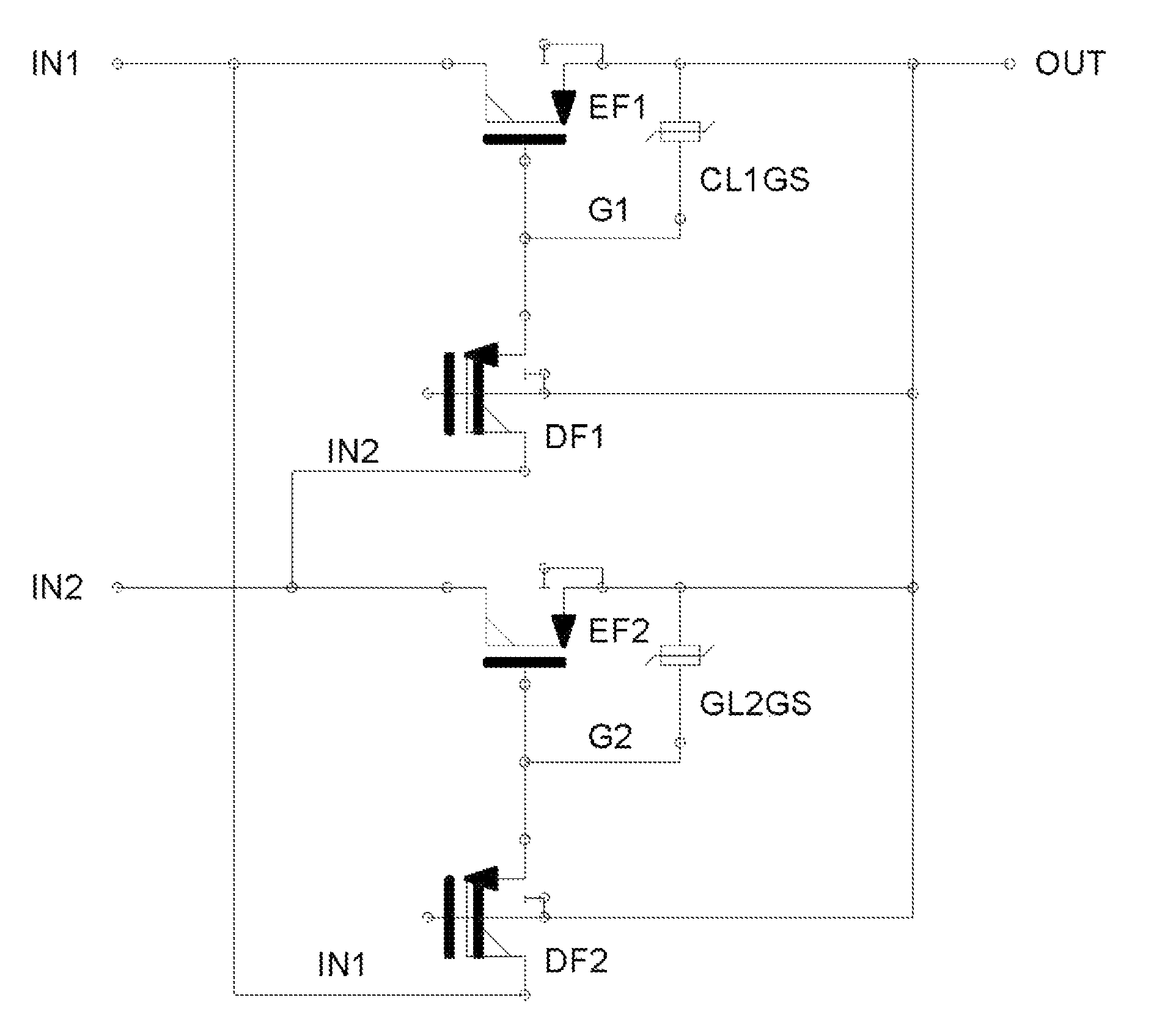
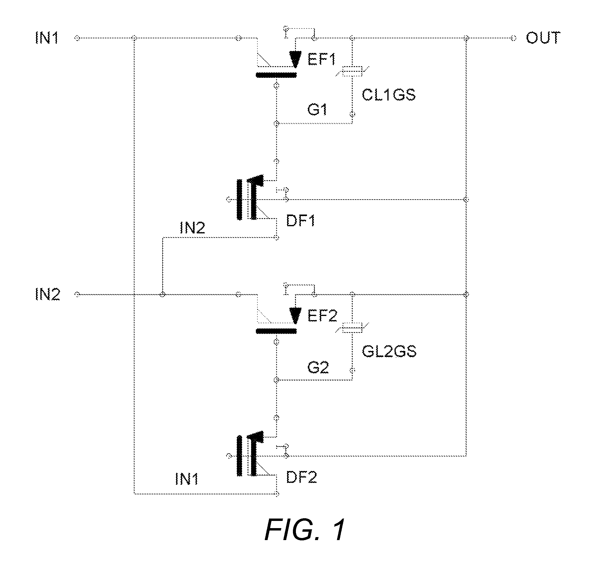
[0025]Maximum voltage selection circuits will now be described that may receive two or more voltages inputs. These circuits may not provide any direct current path between the inputs. Still further, no operational quiescent current may be drawn during operation from any of their inputs. These circuits may be suitable for applications where one of the supplies is a low power source such as a battery or energy harvester.

[0026]By saying that no operational quiescent current may be drawn during operation from any of the inputs, it should be understood that there may still be a very small current, typically a few pico Amperes to a few nano Ampe...


PUM


Abstract

A maximum voltage selection circuit may include multiple inputs, each for receiving a different input voltage, an output for delivering the highest of the input voltages, and a voltage selection circuit. The voltage selection circuit may automatically select the input having the largest voltage magnitude, automatically deliver the voltage at the selected input to the output, and not draw quiescent operating current from any of the inputs. For each and every unique combination of two of the multiple inputs, the voltage selection circuit may include an enhancement mode FET with a channel connected in series between a first input of the unique combination of the two inputs and the output; a connection between the gate of the enhancement mode FET and the second input of the unique combination of the two inputs through the channel of a depletion mode FET; an additional enhancement mode FET with a channel connected in series between the second of the unique combination of the two inputs and the output; and a connection between the gate of the additional enhancement mode FET and the first of the unique combination of the two inputs through the channel of an additional depletion mode FET.

Description

CROSS-REFERENCE TO RELATED APPLICATION[0001]This application is based upon and claims priority to U.S. provisional patent application 62 / 047,432, entitled “High Voltage Maxer Circuit with No Q-Current,” filed Sep. 8, 2014. The entire content of this application is incorporated herein by reference.BACKGROUND[0002]1. Technical Field[0003]This disclosure relates to circuits that automatically select and deliver the highest of multiple different input voltages to an output.[0004]2. Description of Related Art[0005]Some analog systems may need to automatically deliver the maximum of two or more input voltages. A maximum voltage selection circuit may be used for this purpose.[0006]Such a circuit may need to operate continuously. This could impose a continuous load burden, which could be a problem for applications that rely on a battery for operation. A maximum voltage selection circuit that does not draw any quiescent current from any of its inputs or from its output may be highly desirabl...

Claims


Application Information

Patent Timeline
IPC IPC(8): H03K17/00H03K5/1532
CPCH03K5/1532H01L27/0883
Inventor BRENNAN, CIARAN J.KUMAR, MUKESH
Owner ANALOG DEVICES INT UNLTD
Features
  • R&D
  • Intellectual Property
  • Life Sciences
  • Materials
  • Tech Scout
  • Unparalleled Data Quality
  • Higher Quality Content
  • 60% Fewer Hallucinations
Learn More