
Device for using flow energy

a flow energy and energy technology, applied in the direction of wind energy generation, motors, engine fuctions, etc., can solve the problems that the precise guidance of the elements for transmitting the energy of movement at the generator can only be achieved at great structural cost, and achieve the effect of convenient utilization of flow energy, simple construction and less dependence on weather conditions

Inactive Publication Date: 2016-04-12
ANPE A E RENEWABLE POWER SYST NEW TECH
View PDF11 Cites 3 Cited by
  • Summary
  • Abstract
  • Description
  • Claims
  • Application Information

AI Technical Summary

Benefits of technology

The invention is designed to make better use of flow energy while keeping its structure simple and less dependent on weather conditions. Compared to previous devices, the support can be made more compact by having the carriages elastically connected. The elements can also be modular, making transportation easier and more cost-effective. This allows for larger devices to be transported to almost any location with relative ease.

Problems solved by technology

A guidance of the elements sufficiently precise for transmitting the energy of movement at a generator can only be achieved at great structural expense.

Method used


Image

  • Device for using flow energy
  • Device for using flow energy
  • Device for using flow energy

Examples


Embodiment Construction

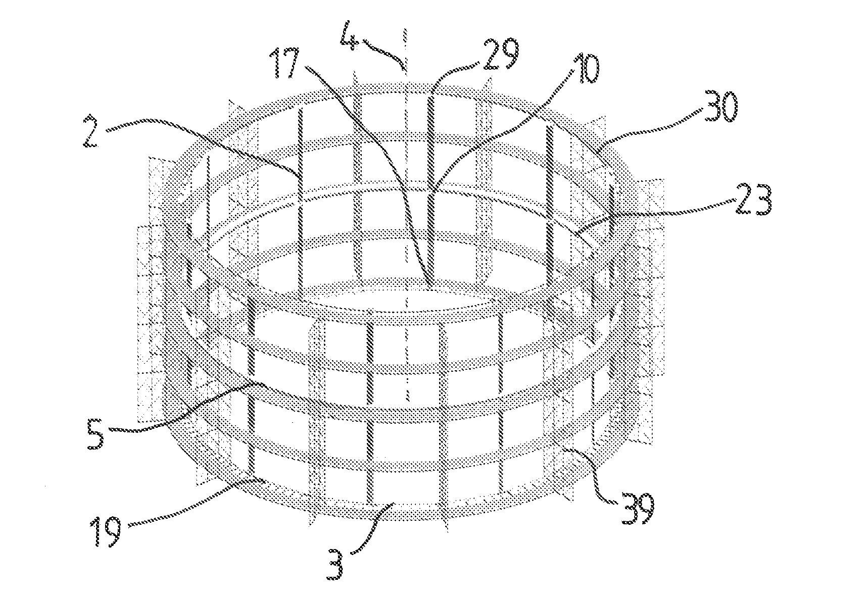
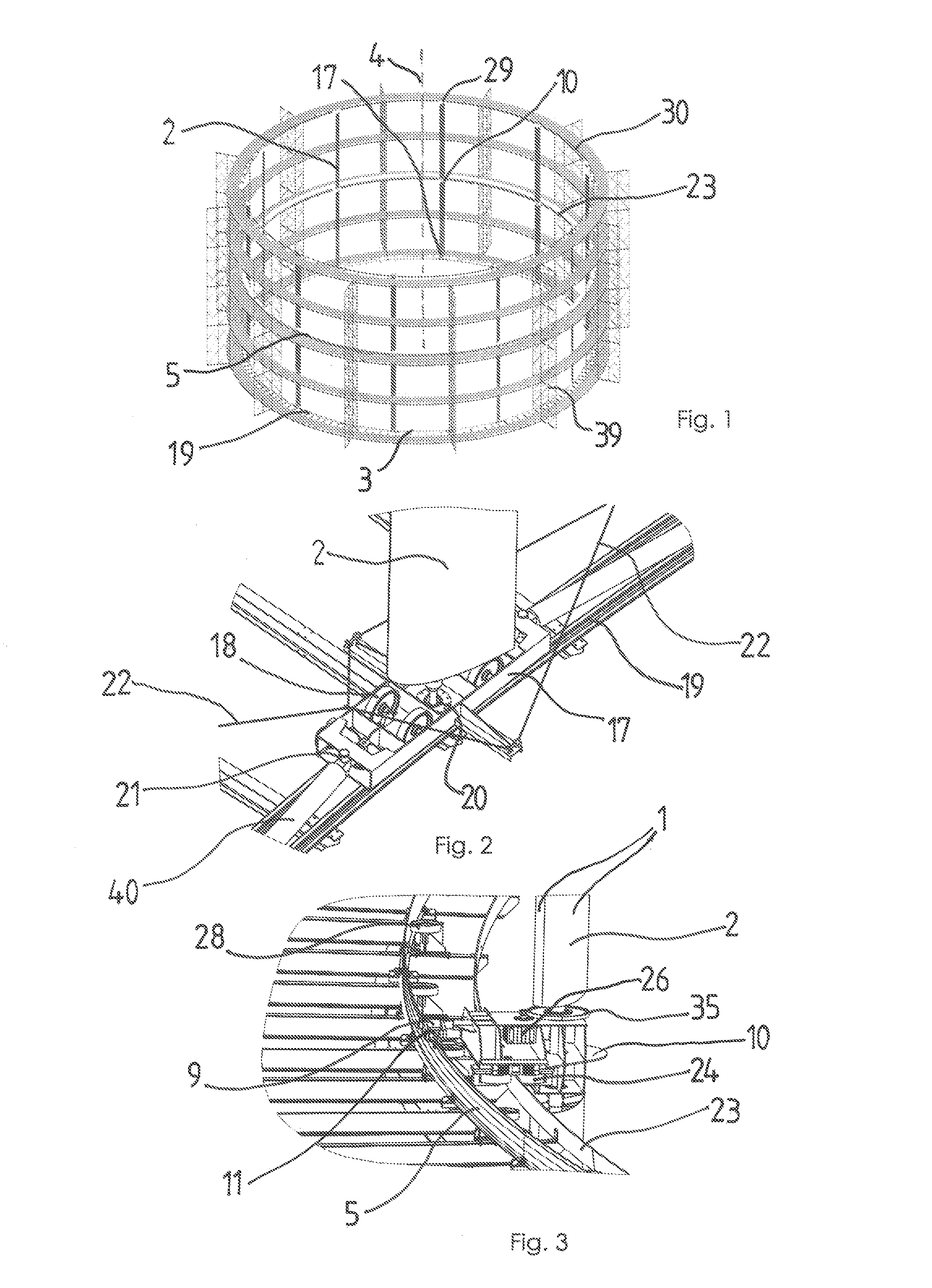
[0036]A device according to the invention according to FIG. 1 includes ten elements 2 with impinged-upon surfaces 1 for picking up wind energy, which elements are arranged on circular rails 19, 23, 30 parallel offset relative to each other along a track 3 so as to be rotatable about an axis 4 shown by a broken line. The device is provided with a scaffold 39 which absorbs the forces transmitted by the elements to rails 19, 23, 30.

[0037]The elements 2 which have a total length of 50 m are of modular construction and composed of four parts, each having a length of 12.5 m, and are arranged lengthwise one above the other.

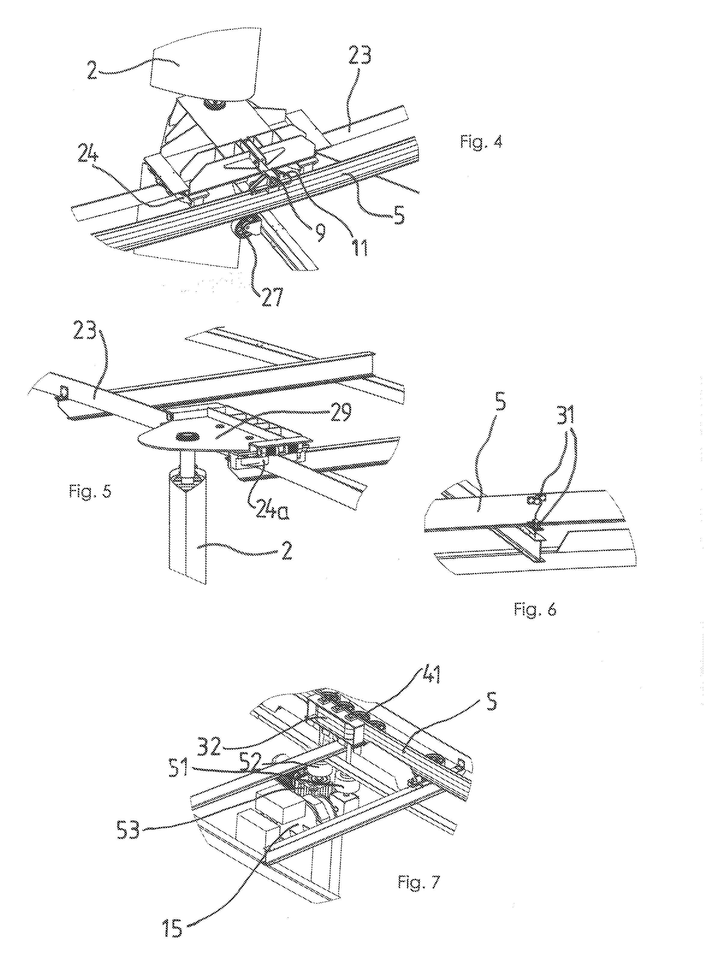
[0038]As shown in FIG. 2, the elements 2 are rotatably supported in a ball head bearing 20 on a carriage 17 arranged on the rails 19. The carriage 17 has four rollers 18, wherein always two of the rollers travel on one of the two rails 19. In addition, ropes 22 are fastened to the carriage 17 which are connected with a middle or upper support of the elements 2 (not shown...


PUM


Abstract

The invention relates to a device for using flow energy, in particular wind energy, comprising elements (2) that have incident-flow surfaces (1) and that are guided so as to circulate on a track at a distance to each other, wherein a rotational axis about which the elements (2) move is arranged perpendicularly to the flow direction, and comprising an apparatus (5) for transmitting the flow energy captured using the elements (2) to a generator (15). According to the invention, the apparatus (5) and the elements (2) are connected to each other in such a way that forces acting tangentially to the track (3) are transmitted and forces acting in other directions are not transmitted or are transmitted only in an attenuated manner.

Description

[0001]The present application is a 371 of International application PCT / DE2010 / 001515, filed Dec. 19, 2010, which claims priority of DE 10 2009 060 437.5, filed Dec. 22, 2009, the priority of these applications is hereby claimed and these applications are incorporated herein by reference.BACKGROUND OF THE INVENTION[0002]The invention relates to a device for utilizing flow energy, particularly wind energy, with elements provided with impinged-upon surfaces, wherein the elements circulate on a track and are guided at a distance relative to each other, wherein an axis of rotation around which the elements move is arranged transversely of the flow direction, and comprising a device for transmitting the flow energy picked up by the elements to a generator[0003]Such a device is known from WO 2007 / 118462 A1. The elements are moved parallel relative to each other and, contrary to a conventional wind wheel, are not arranged in a plane perpendicularly of the flow direction. They are fastened ...

Claims


Application Information

Patent Timeline
IPC IPC(8): F03D9/00H02P9/04F03D5/04F03D3/06
CPCF03D5/04F03D3/062F05B2220/7068F05B2240/211F05B2260/4031Y02E10/70Y02E10/74
Inventor KELAIDITIS, KONSTANTINKELAIDITIS, NIKOLASKELAIDITIS, ALEXIS
Owner ANPE A E RENEWABLE POWER SYST NEW TECH
Learn More