Non-adjustable pointer-tracker gimbal used for directed infrared countermeasures systems

a pointer-tracker gimbal and infrared countermeasure technology, applied in direction/deviation determining electromagnetic systems, instruments, optical elements, etc., can solve the problems of not being able to easily compensate for positional errors of mirrors, not being able to adjust for all pointing directions, and complicating the situation of how to lock the adjustment mechanism

Active Publication Date: 2016-04-12
BAE SYST INFORMATION & ELECTRONICS SYST INTERGRATION INC
View PDF42 Cites 4 Cited by
  • Summary
  • Abstract
  • Description
  • Claims
  • Application Information

AI Technical Summary

Benefits of technology

[0027]In summary, a system is provided to assure that the laser beam from a DIRCM head or gimbal places laser energy on the target without complicated adjustments, and expensive parts. This is accomplished by providing a uni-constructed elevation arm with both input and output mirrors fixed to it, and an aim-point map that compensates for all manufacturing tolerances to gain the end objective of jamming heat-seeking ...

Problems solved by technology

In directed infrared countermeasures (DIRCM) systems there has always been a problem of making the line-of-sight (LOS) to the target and the laser beam that is emitted from the DIRCM head coincident or parallel.
While there have been many efforts to reduce the amount of parallax between the two and therefore reduce the aiming errors of the outgoing laser beam, the difficulty in the past has always been with the multiple mirrors that are utilized both for positioning the received image at the center of a focal plane array and for directing the laser beam out the DIRCM head.
While it is possible for one pointing direction to adjust out the parallax by adjusting all the mirrors, the adjustment does not correct for all pointing directions.
Since these mirrors move independently, the positional errors of the mirrors add up and are not easily compensated for ov...

Method used


Image

  • Non-adjustable pointer-tracker gimbal used for directed infrared countermeasures systems
  • Non-adjustable pointer-tracker gimbal used for directed infrared countermeasures systems
  • Non-adjustable pointer-tracker gimbal used for directed infrared countermeasures systems

Examples


Embodiment Construction

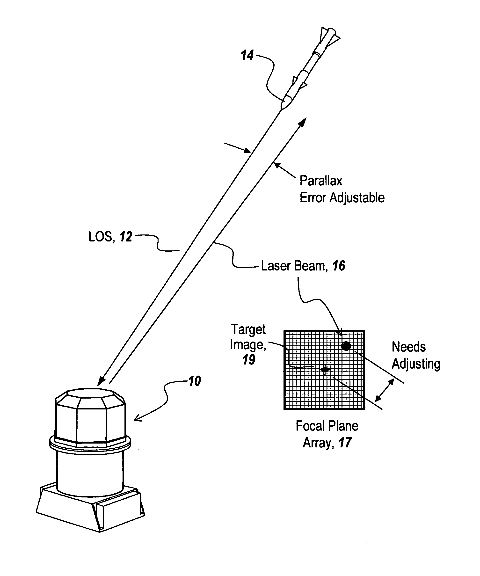
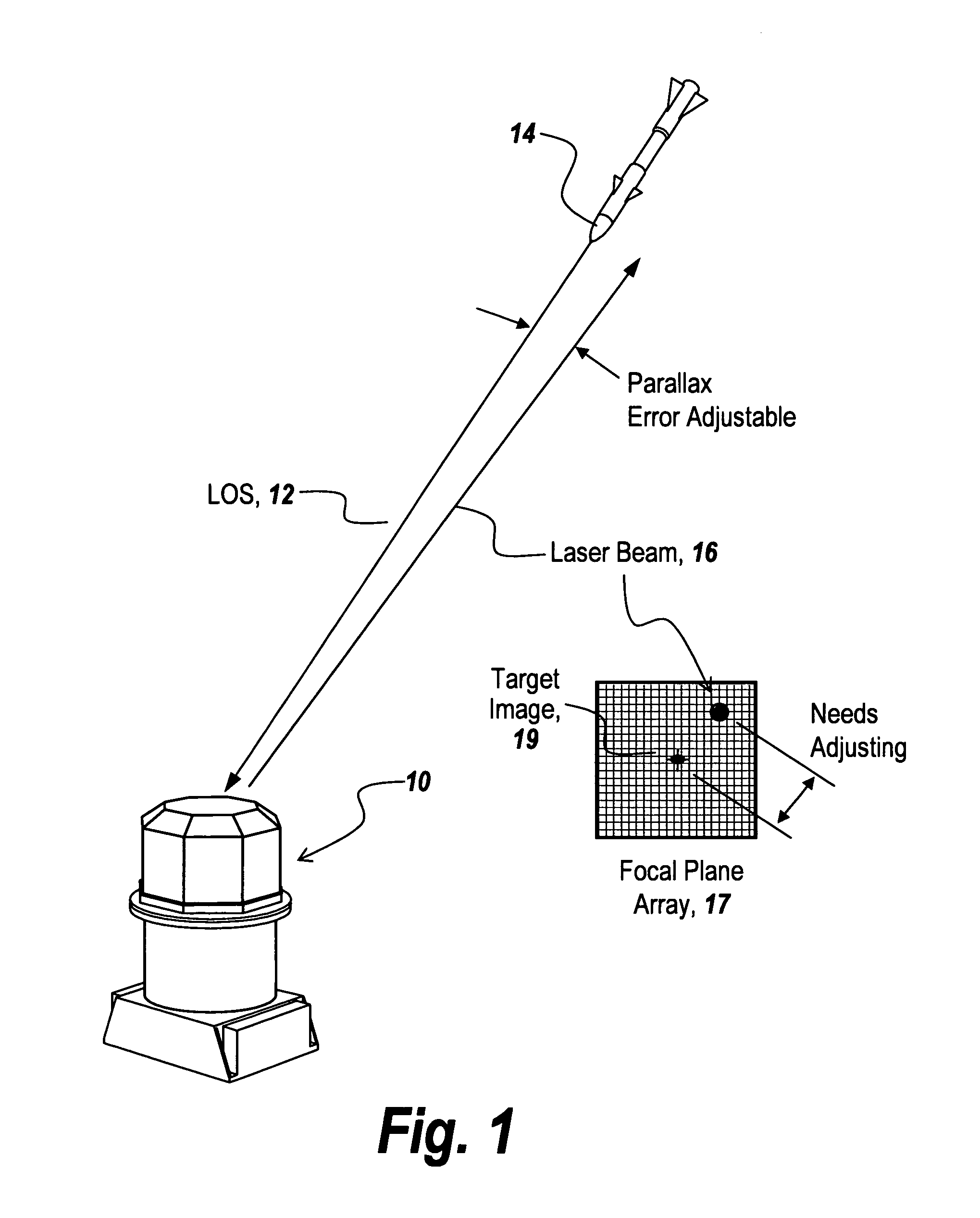
[0039]Referring now to FIG. 1, a pointer-tracker gimbal 10 is utilized to detect the line-of-sight 12 to a target 14 and aim a laser beam 16 towards the head of the missile.

[0040]Pointing accuracies required for such pointer-trackers are substantial. The pointing accuracies required to assure a hit on the target must be less than the total errors within the system, namely in one embodiment a 200 microradian divergence between the line-of-sight to the target and the projected laser beam. As illustrated, the laser beam path 16 and the line-of-sight to the true target 14 must be brought into alignment as would be the case with a coincidence of the back projection of the laser 16 beam with target image 19 on focal plane array 17. This is done by adjustments that must be maintained during the harsh environment of military aircraft.

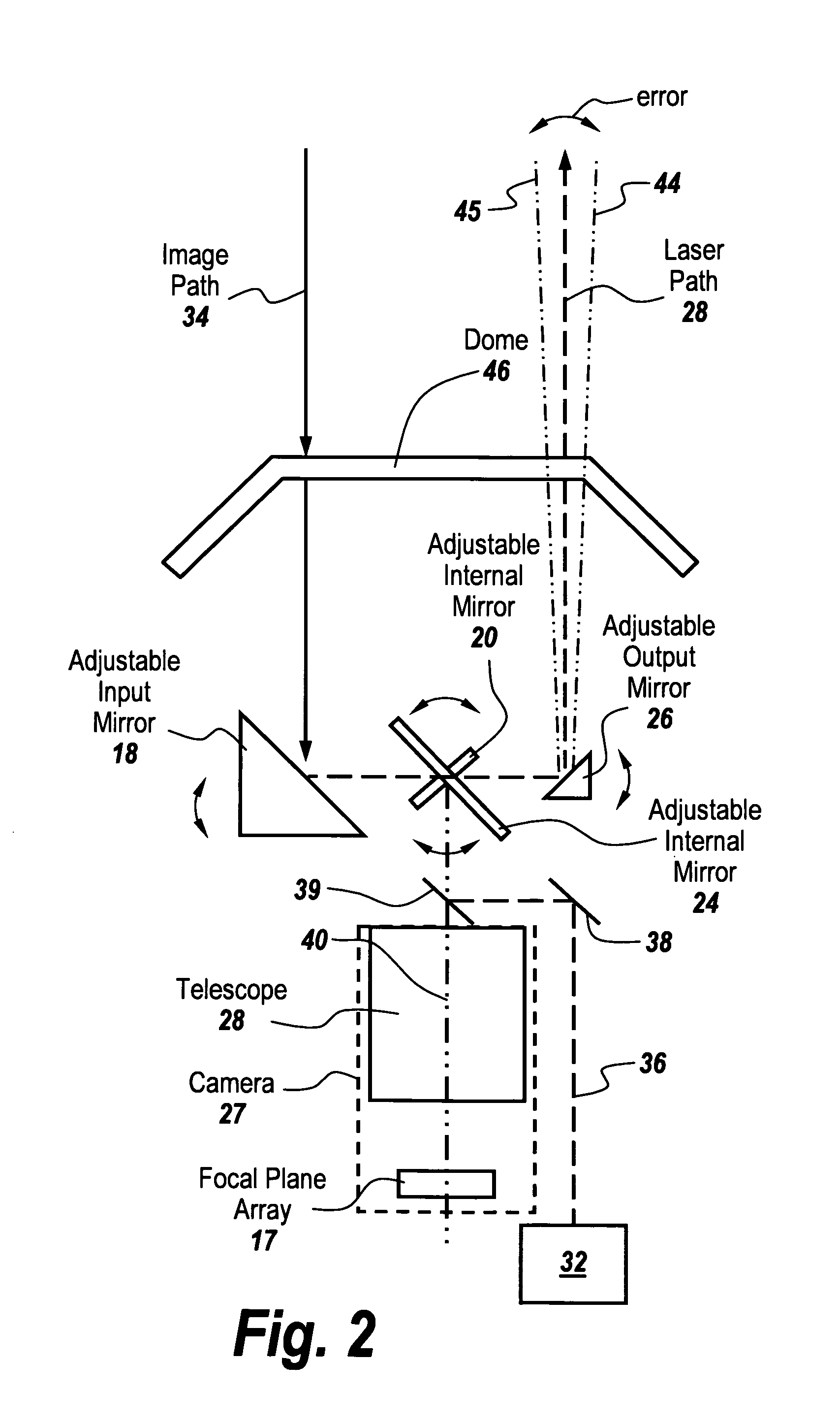
[0041]This stringent requirement in and of itself is extremely difficult to achieve and as shown in FIG. 2, gimbals require individually adjustable mirrors, na...


PUM


Abstract

In a directed infrared countermeasure system, to assure parallelism between the line-of-sight to a target and the output beam, the input and output mirrors are fixedly attached to a uni-construction arm mounted to a rotatable azimuth platter to which internal mirrors are also fixedly attached. A system is provided for zeroing out alignment errors by developing an aim-point map for the gimbal that records initial alignment errors induced by manufacturing tolerances and uses the aim-point map error values to correct the output mirror orientation. The system also corrects for alignment errors induced by thermal gradients.

Description

RELATED APPLICATIONS[0001]This Application is a continuation of co-pending U.S. patent application Ser. No. 13 / 373,775 filed Nov. 30, 2011 now abandoned which is a continuation of U.S. patent application Ser. No. 12 / 499,584 filed Jul. 8, 2009 now abandoned. This Application claims rights under 35 USC §119(e) from U.S. Application Ser. No. 61 / 134,277 filed Jul. 8, 2008, the contents of which are incorporated herein by reference.FIELD OF THE INVENTION[0002]This invention relates to directed infrared countermeasures and more particularly to a non-adjustable pointer-tracker gimbal for use in such systems.BACKGROUND OF THE INVENTION[0003]In directed infrared countermeasures (DIRCM) systems there has always been a problem of making the line-of-sight (LOS) to the target and the laser beam that is emitted from the DIRCM head coincident or parallel. While there have been many efforts to reduce the amount of parallax between the two and therefore reduce the aiming errors of the outgoing laser...

Claims


Application Information

Patent Timeline
IPC IPC(8): G01B11/26
CPCG01B11/26G01S3/7803G01S3/786G01S7/495G02B7/1827F41H13/005F41G7/224
Inventor CORELLA, ARMANDOBUZDAR, LYNNE F.GIDSEG, RONALD A.
Owner BAE SYST INFORMATION & ELECTRONICS SYST INTERGRATION INC
Why Eureka
Try Eureka