System and method for conducting electromagnetic resonant cavity inspection of gun barrels

a technology electromagnetic resonant cavity, which is applied in the field of electromagnetic resonant cavity inspection of gun barrels, can solve the problems of change the electrical properties of the tube bore (or cavity), and inability to meet the requirements of the application, so as to achieve greater effect of quality factor q, change in material properties, and effect on cavity efficiency

Active Publication Date: 2016-04-12
UNITED STATES OF AMERICA THE AS REPRESENTED BY THE SEC OF THE ARMY
View PDF1 Cites 6 Cited by
  • Summary
  • Abstract
  • Description
  • Claims
  • Application Information

AI Technical Summary

Benefits of technology

When a gun is fired, there are significant changes in the materials used for the protection against damage from firearms. These changes can impact how well the weapon works by changing the way energy is lost during firing. A measurement called the quality factor helps determine how effective the design is at reducing these losses. With repeated use, the changes become even more important because they make it harder for the device to work efficiently.

Problems solved by technology

The technical problem addressed in this patent text is the development of a better way to evaluate the condition of guns and their components. Current methods involve expensive, time-consuming processes like viscosity testing and inspecting materials through ultrasonic imaging. There is a need for a more efficient and accurate solution to help ensure optimal weapon readiness and prevent failures caused by damaged or worn parts.

Method used


Image

  • System and method for conducting electromagnetic resonant cavity inspection of gun barrels
  • System and method for conducting electromagnetic resonant cavity inspection of gun barrels
  • System and method for conducting electromagnetic resonant cavity inspection of gun barrels

Examples


Embodiment Construction

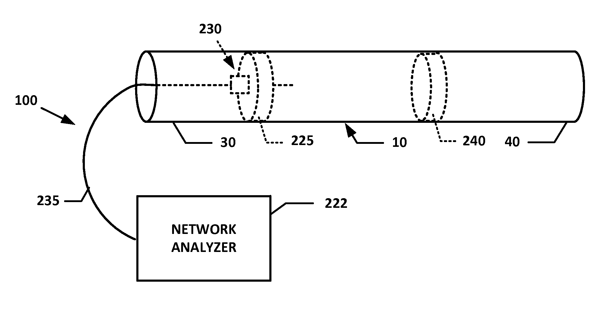
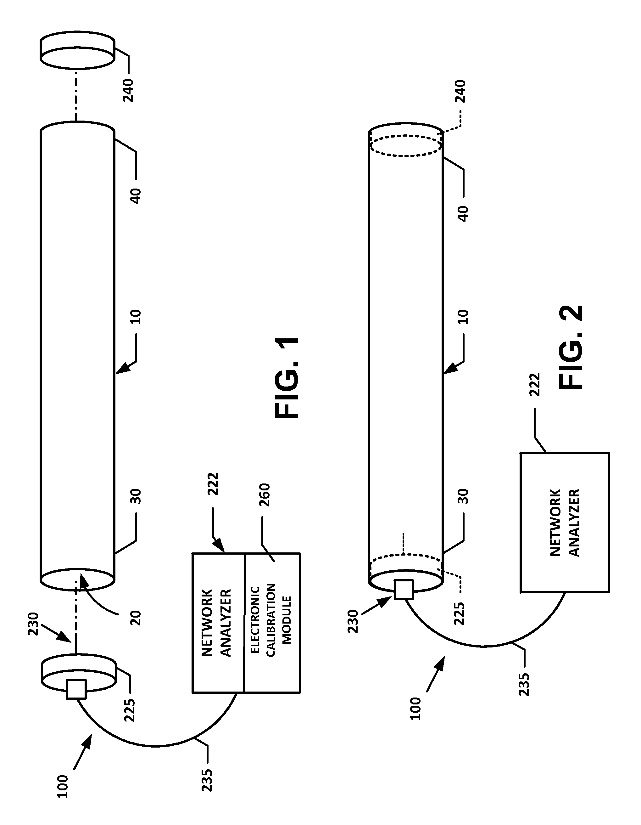
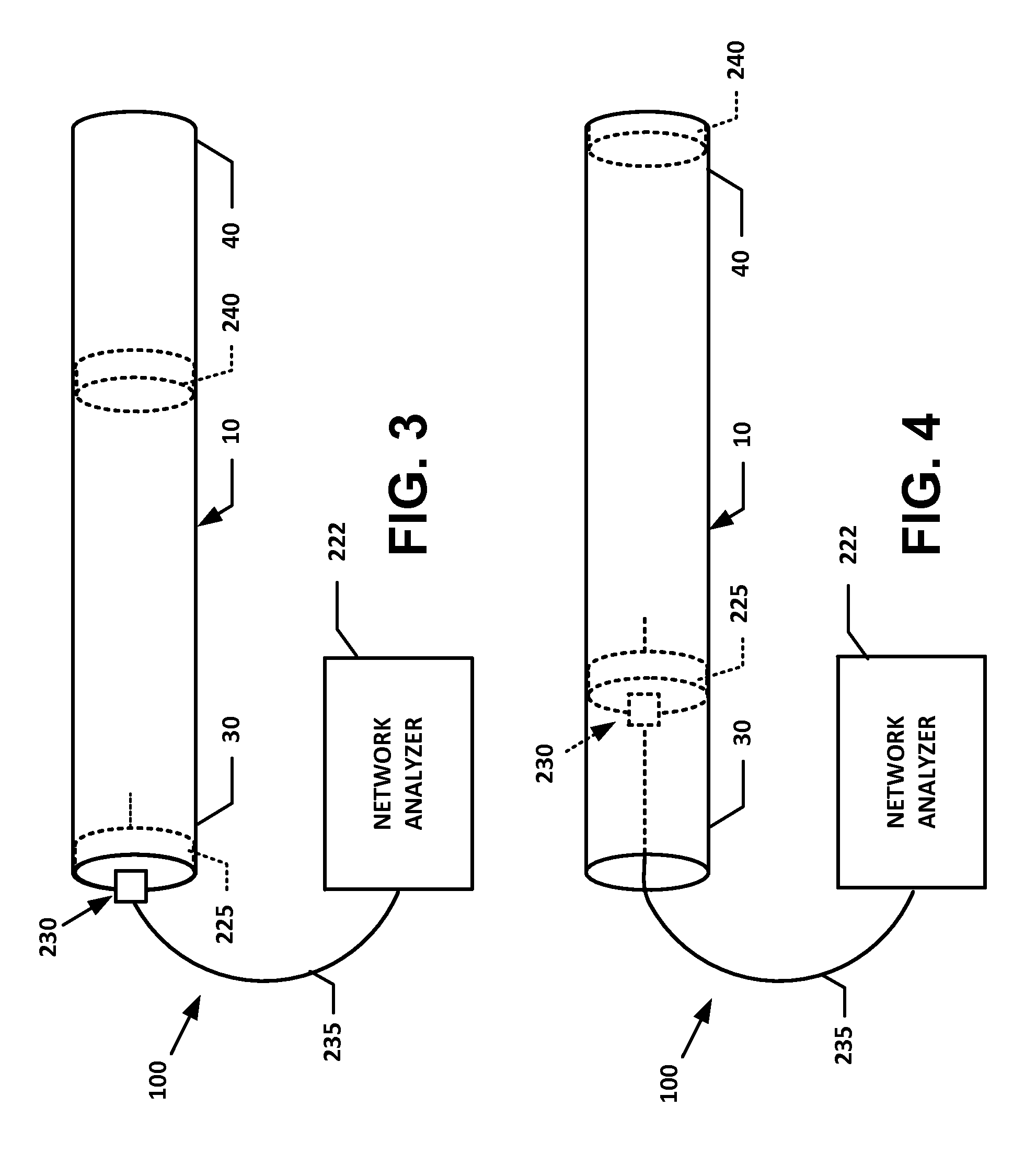
[0045]FIG. 1 illustrates an exemplary electromagnetic resonant cavity system 100 shown prior to assembly to a gun tube 10 to be inspected, according to a first preferred embodiment of the present invention. The system 100 offers a new technique for evaluating the condition of the gun tube 10, by monitoring the resonance responses that evolve from microwave signals introduced into a bore 20 of the gun tube 10.

[0046]The system 100 presents numerous advantages, among which are the following: it is relatively simple to implement; it measures the degradation of the inner surface of the bore 20 that results from firing; it is sensitive to small surface defects; it is sensitive to small changes in the geometry of the tube; and it quickly and automatically determines if the safety and performance of the gun tube 10 have been compromised by firing damage or by an excessive number of fatigue cycles.

[0047]To this end, the system 100 generally includes a network analyzer 222 that is connected t...


PUM


Abstract

A system and associated method for quickly and automatically determining if the safety and performance of a gun tube have been compromised by firing damage or by an excessive number of fatigue cycles. An electromagnetic resonant cavity inspection provides a means of rapidly evaluating the health of the gun tube by monitoring the resonant frequencies that evolve from microwave signals introduced into the cavity or bore of the gun tube. This approach exploits the high sensitivity of the electromagnetic cavity resonance phenomena. Defects and degradation in the structure's cavity produce quantifiable changes in the quality factor, frequency shifts, and mode splitting.

Description


Claims


Application Information

Patent Timeline
Owner UNITED STATES OF AMERICA THE AS REPRESENTED BY THE SEC OF THE ARMY
Why Eureka
Try Eureka