System for charging an energy store, and method for operating the charging system

a technology for charging energy and energy storage, applied in the direction of parallel/serial switching, battery/fuel cell control arrangement, transportation and packaging, etc., can solve the problem of not having dc voltage available for supplying energy directly to electrical loads

Active Publication Date: 2016-04-12
ROBERT BOSCH GMBH
View PDF12 Cites 5 Cited by
  • Summary
  • Abstract
  • Description
  • Claims
  • Application Information

AI Technical Summary

Benefits of technology

[0014]In such an assemblage, the first DC voltage converter—which can be embodied, depending on the application, as a step-up converter, step-down converter, or even as a step-up / down converter, e.g. in the form of an inverse converter—can control the energy flux out of the controllable energy reservoir in such a way that a constant power output is taken off. The result of this is that the voltage at the link circuit capacitor no longer fluctuates, and can be selected optimally for the specific application. In addition, no phases without current flow occur, so that sufficient buffering can be achieved even with a link circuit capacitor of comparatively small dimensions.
[0016]This allows a dual-voltage energy supply network to be realized, in which context the voltage level of the second energy reservoir is held relatively constant by a battery management system so that the second DC voltage converter can be designed for a narrow range of input and output voltages and thus with a single stage, resulting in reduced hardware outlay.
[0019]Lastly, the first DC voltage converter can also be embodied with galvanic isolation, and the second energy reservoir can be embodied as a low- or medium-voltage energy reservoir. If the second energy reservoir is designed for a voltage≦60 V, this then has the advantage that no additional safeguarding measures, for example regarding shock hazard protection, need to be taken; this yields cost savings. A prerequisite is of course that none of the electrical loads requires a higher operating voltage level.
[0022]Regardless of whether a bridge rectifier or N-pulse rectifier is used, the connection between the reference bus of the controllable energy reservoir and the reference bus of the charging device has the advantage that with this configuration, the link circuit of the energy supply network can be provided with voltage even when the electrical machine is at a standstill. An identical DC voltage can thus be established in each energy supply branch of the controllable first energy reservoir, and fed directly into the link circuit. The voltage in each energy supply branch is advantageously regulated in order to avoid compensating currents in the electrical machine.
[0023]According to a further embodiment of the invention, the rectifier unit can also be embodied as a bidirectional rectifier. Bidirectional operation of a rectifier can be achieved either by the fact that controllable switch elements are inserted parallel to the diodes of a diode rectifier, or also by the fact that the diodes are entirely replaced by controllable switch element. The use of bidirectional rectifiers offers the advantage that the energy supply cells of the controllable first energy reservoir can then also be charged by way of the second energy reservoir.

Problems solved by technology

In contrast to conventional systems, however, in which an electrical machine is controlled via an inverter and is supplied with electrical energy by an electrical energy reservoir separate therefrom, no DC voltage is available for supplying energy directly to electrical loads such as, for example, high-voltage loads in a vehicle electrical system, or as an input variable for a DC voltage converter.

Method used


Image

  • System for charging an energy store, and method for operating the charging system
  • System for charging an energy store, and method for operating the charging system
  • System for charging an energy store, and method for operating the charging system

Examples


Embodiment Construction

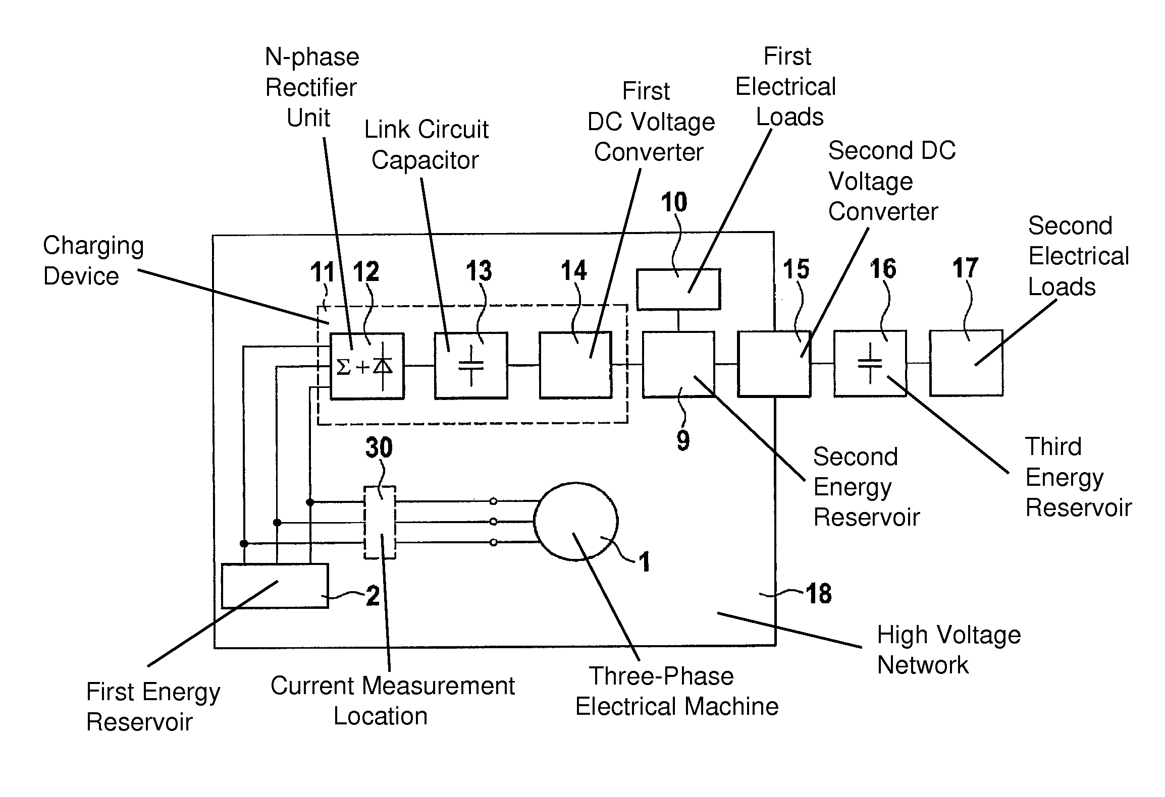
[0032]FIG. 1 is a schematic block diagram of a first embodiment of an energy supply network according to the present invention. A controllable energy reservoir 2 is connected to a three-phase electrical machine 1. Controllable energy reservoir 2 encompasses three energy supply branches 3-1, 3-2, and 3-3, which are connected on the one hand to a low reference potential T- (reference bus) and on the other hand respectively to individual phases U, V, W of electrical machine 1 (see FIGS. 4, 5, 6, 7). Each of energy supply branches 3-1, 3-2, and 3-3 has, connected in series, m energy reservoir modules 4-11 to 4-1m, 4-21 to 4-2m, and 4-31 to 4-3m respectively, where m≧2. Energy reservoir modules 4 in turn each encompass multiple electrical energy reservoir cells connected in series which, for reasons of clarity, are labeled in FIGS. 4 to 7 only in energy supply branch 3-3 connected to phase W of electrical machine 1, with reference characters 5-31 to 5-3m. Energy reservoir modules 4 furth...


PUM


Abstract

An energy supply network has an n-phase electrical machine where n≧1 and a controllable first energy reservoir which serves to control and supply electrical energy to the electrical machine. The first energy reservoir has n parallel energy supply branches that each have at least two energy reservoir modules, connected in series, that each encompass at least one electrical energy reservoir cell having an associated controllable coupling unit and are connected on the one hand to a reference bus, and on the other hand to a respective phase of the electrical machine. As a function of control signals, the coupling units either bypass the respectively associated energy reservoir cells or switch the respectively associated energy reservoir cells into the energy supply branch.

Description

BACKGROUND OF THE INVENTION[0001]1. Field of the Invention[0002]The present invention relates to a system for charging an energy reservoir, and to a method for operating the charging system.[0003]2. Description of the Related Art[0004]It is becoming apparent that in the future, both for stationary applications such as wind power installations and in vehicles such as hybrid or electric vehicles, increasing use will be made of electronic systems that combine new energy storage technologies with electrical drive technology. In conventional applications an electrical machine, which is embodied e.g. as a phase-sequence machine, is controlled via a converter in the form of an inverter. A characteristic of such systems is a so-called DC link circuit through which an energy reservoir, usually a battery, is connected to the DC voltage side of the inverter. In order to be able to meet the demands of a particular application in terms of power output and energy, multiple battery cells are conne...

Claims


Application Information

Patent Timeline
Patent Type & Authority Patents(United States)
IPC IPC(8): H02J1/00H02J7/14H02J7/00B60L11/18H02P27/14
CPCB60L11/1866H02J7/0014H02J7/0024H02J7/0055H02J7/1492H02P27/14H02J1/00B60L11/1853B60L11/1864H02J2007/0059H02J2007/0067Y02T10/642Y02T10/7005Y02T10/7055Y02T10/7061Y02E10/766Y10T307/32Y10T307/313Y02T10/92B60L58/18B60L58/21B60L58/22H02J2207/20H02J2207/40H02J2310/48H02J2300/28H02J7/0025Y02T10/64Y02T10/70Y02E10/76
Inventor FEUERSTACK, PETERWEISSENBORN, ERIKKESSLER, MARTIN
Owner ROBERT BOSCH GMBH
Why Eureka
Try Eureka