
Signaling of the active safety position of electropneumatic position regulators

a technology of position regulator and active safety position, which is applied in the direction of valve operation/release device, service pipe system, transportation and packaging, etc., can solve the problems of inability to observe the signaling form explained above accurately or not, and it is difficult for the operator to ascertain which position regulator is affected

Inactive Publication Date: 2012-11-20
ABB TECH AG
View PDF13 Cites 2 Cited by
  • Summary
  • Abstract
  • Description
  • Claims
  • Application Information

AI Technical Summary

Benefits of technology

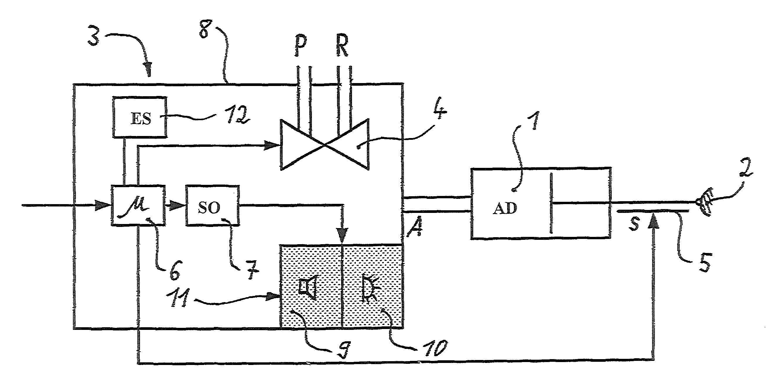
"The patent describes an electropneumatic position regulator that can control a pressure-medium-operated actuating drive. It includes an electronic control unit that can safely shut down the actuating drive in case of a fault. The regulator also has a downstream signal output unit that generates a binary fault signal when the electronic control unit shuts down. This signal is then transformed into an audible or visual signal outside the regulator's housing, alerting operators to the problem. The technical effect of this invention is to provide a safer and more reliable position regulator for controlling pressure-medium-operated actuating drives."

Problems solved by technology

However, the solutions from the conventional art as described above have a disadvantage in that, when the position regulator is viewed from further away, the forms of signaling explained above cannot be observed accurately or at all.
Particularly in operating situations in which a plurality of position regulators with actuating drives are arranged alongside one another, even if it is known that one of these position regulators is faulty, it is difficult for the operator to ascertain which of the position regulators is affected by the fault condition.

Method used


Image

  • Signaling of the active safety position of electropneumatic position regulators
  • Signaling of the active safety position of electropneumatic position regulators

Examples


Embodiment Construction

[0017]Exemplary embodiments of the present disclosure provide an improved electropneumatic position regulator, which can assume a safety position in the event of a fault, such that the assumed safety position can also be perceived by human senses from further away, relative to the physical location of the position regulator.

[0018]According to an exemplary embodiment, when a locally integrated electronic control unit in the position regulator determines the existence of an assumed safety position, a downstream signal output unit, which can act as a driver stage, can generate at least one binary fault signal to be indicated in an externally perceptible manner by visual and / or audible signaling means fitted, for example, to an external housing of the position regulator.

[0019]An advantageous feature of various exemplary embodiments provided herein is that the power of the driver stage makes it possible to produce a very strong notification signal (audible and / or visual), which can be pe...


PUM


Abstract

An electropneumatic position regulator for controlling a pressure-medium-operated actuating drive to which compressed air can be applied via a working connection of the actuating drive. Compressed air is made available to the position regulator via a feed pressure connection, and the pressure regulator includes an electronic control unit configured to assume a safety position in the event of a fault. When the electronic control unit assumes a safety position, a downstream signal output unit, which acts as a driver stage, generates at least one binary fault signal which is indicated in an externally perceptible manner (e.g., visually and / or audibly) by at least one signaling device fitted externally to a housing of the position regulator.

Description

RELATED APPLICATION[0001]This application claims priority under 35 U.S.C. §119 to German Patent No. 10 2008 033 047.7 filed in Germany on Jul. 14, 2008, the entire content of which is hereby incorporated by reference in its entirety.FIELD[0002]The present disclosure relates to an electropneumatic position regulator for controlling a pressure-medium-operated actuating drive to which compressed air can be applied via a working connection A of the actuating drive, which compressed air is made available to the position regulator via a feed pressure connection P, with means being provided for assuming a safety position in the event of a fault. The present disclosure also relates to an actuating drive to which compressed air can be applied and which is equipped with such an electropneumatic position regulator.BACKGROUND INFORMATION[0003]An exemplary field of use of such position regulators can be position control of actuating or control drives. In this case, an electrical nominal value is...

Claims


Application Information

Patent Timeline
Patent Type & Authority Patents(United States)
IPC IPC(8): F16K31/44
CPCF15B19/005Y10T137/7761Y10T137/8326
Inventor TABELANDER, STEFAN
Owner ABB TECH AG
Learn More