Contactless data communications coupling
a data communication and contactless technology, applied in waveguide type devices, surveying, wellbore/well accessories, etc., can solve the problems of high transmission loss, slow rate, and difficult bi-directional data communication, and achieve high transmission loss
- Summary
- Abstract
- Description
- Claims
- Application Information
AI Technical Summary
Benefits of technology
Problems solved by technology
Method used
Image
Examples
first embodiment
[0084]In this first particular embodiment, the transmission line 65 is an unbalanced coaxial cable, i.e. a coaxial cable comprising one inner conductor 651 and one outer conductor 652, with a characteristic impedance in the range of about 30 to about 120 ohms, most preferably with a characteristic impedance in the range of 50 to 75 ohms. In this first embodiment, the coaxial cable has transmission losses less than 1.67 dB / 10 m for frequencies below 500 MHz.
[0085]In FIG. 6a, each of the first 40a and second 41a half-couplers is shown with the appropriate layer of dielectric material removed (83a and 87a, respectively), so as to reveal the shape of each of the conducting strips 82a and 88a beneath.
[0086]In this first particular embodiment, each of the conducting strips 82a and 88a has the shape of a split ring comprising a gap 821a and 881a, respectively. These gaps allow the desired coupling characteristics to be established. In order to ensure efficient coupling, the size of each ga...
second embodiment
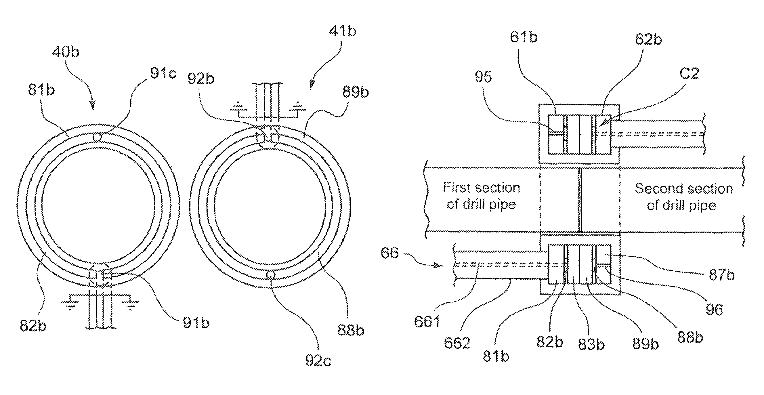
[0103]In this second particular embodiment, the transmission line 66 is an unbalanced coaxial cable, i.e. a coaxial cable comprising one inner conductor 661 and one outer conductor 662, with a characteristic impedance in the range of about 30 to about 120 ohms, most preferably with a characteristic impedance in the range of 50 to 75 ohms. In this second embodiment, the coaxial cable has transmission losses less than 1.67 dB / 10 m for frequencies below 500 MHz.
[0104]As shown in the example of FIG. 8b, the multi-layer disc of dielectric material of the first half-coupler 40b comprises a rear layer 81b of dielectric material extending in the bottom of the first housing 61b and a front layer 83b of dielectric material extending around the opening of the first housing 61b. The multi-layer disc of dielectric material of the second half-coupler 41b comprises a rear layer 87b of dielectric material extending in the bottom of the second housing 62b and a front layer 89b of dielectric material...
third embodiment
[0112]In this third particular embodiment, the transmission line 67 is a balanced coaxial cable (also called “coax twin”), i.e. a coaxial cable comprising a first inner conductor 671, a second inner conductor 672 and one outer conductor 673, with a characteristic impedance in the range of about 50 to about 180 ohms, most preferably with a characteristic impedance in the range of 100 to 150 ohms. In this third embodiment, the coax twin has transmission losses less than 1.67 dB / 10 m for frequencies below 500 MHz.
[0113]In FIG. 9a, each of the first and second half-couplers 40c and 41c is shown with the appropriate layer of dielectric material removed (83c and 87c, respectively) so as to reveal the shape of each of the conducting strips 82c, 82d, 88c and 88d beneath.
[0114]In this third particular embodiment, each half-coupler comprises two portions of ring. In the example of FIG. 9a, each portion of ring has the shape of a half-ring. The first half-coupler 40c comprises two half-rings 8...
PUM
 Abstract
Description
Claims
Application Information
 - R&D
- Intellectual Property
- Life Sciences
- Materials
- Tech Scout
- Unparalleled Data Quality
- Higher Quality Content
- 60% Fewer Hallucinations
Browse by: Latest US Patents, China's latest patents, Technical Efficacy Thesaurus, Application Domain, Technology Topic, Popular Technical Reports.
© 2025 PatSnap. All rights reserved.Legal|Privacy policy|Modern Slavery Act Transparency Statement|Sitemap|About US| Contact US: help@patsnap.com


